Described in the device is intended to control the parameters interrupter-distributor ignition system and the rotational speed of the crankshaft automotive engine. When their deviation from the norm serves light and beeps, reminding the driver of the need for the appropriate adjustments node of a circuit breaker or switch to another gear to reduce consumption of fuel.
Most domestic cars VAZ, AZLK, GAS and equipped ZAZ classic ignition system, the Central node which is the interrupter-distributor [1]. On its technical condition and adjustments heavily dependent on the traction characteristics of the engine and consequently the flow fuel. The main parameters of this node is the angle of the closed state of the contacts (USSC) breaker and electrical resistance. The deviation of these parameters from norms leads to the loss of power spark that causes incomplete combustion of fuel. The control of these parameters is quite complex, so many drivers just ignore them, preferring to pay the excess fuel and testing difficulties in starting the engine at low ambient temperatures air.
Meanwhile, in operation, the motor electrical signal from the circuit breaker (Fig. 1) contains all the information necessary not only to measure the above-mentioned parameters, but also to measure USSC all four cylinders. This allows us to calculate deviation angles from the mean and, thus, indirectly assess the condition of the breaker Cam and the degree of wear of the roller. (It should be noted, a problem may occur not only due to wear, for example, because insufficient lubrication of the parts of the dispenser, but with the weakening of fasteners adjustment components due to vibration). In addition, the signal from the interrupter to determine the frequency of rotation of the crankshaft of the engine. If she excessively small when the movement enabled transmission or, conversely, too great, the engine also works suboptimal and consume extra fuel. This situation demonstrates the need to shift into a lower gear in the first case, or at higher in the second.
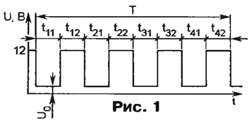
As can be seen from Fig. 1, the contact resistance is characterized by the voltage U0 (it directly proportional to the resistance). USSC and for each of the cylinders can to calculate (in degrees) by the formula α = 90ti1/(ti1+ti2); and the frequency of rotation crankshaft engine F (rpm) - according to the formula

where i is the number of cylinders.
Schematic diagram of the detector shown in Fig. 2. It is based on MK Z86E0208PEC (DD1), specifies the clock frequency of the quartz resonator ZQ1 frequency 8 MHz. Powered device from the 12 volt battery of the vehicle via parametric voltage regulator R1VD1. For the attenuation in the circuit food is provided for oxide ceramic capacitor C1 and C2.
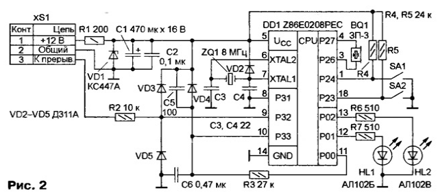
The input signal is applied through an amplitude limiter R2VD3VD5 the output P32 port P3, which reinvestiruet the entrance of one of the two built-in Comparators MK [2] At the conclusion RSS is common to the inverting inputs of both comparator signal from the integrating circuit R3C6, providing the function analog-to-digital conversion [2].
The software processing of received signals is issued for LEDs HL1, HL2 and audio system BQ 1 connected directly to the terminals of R26 and P27 port P2.
Based on the results of measurements of the device generates the following signals:
green signal light (HL2) at a sufficiently low contact resistance breaker and when the value of the average values of USSC breaker and its variation for different cylinders are within normal limits;
- red light signal (HL1) when the deviation of these values from the norm, testifying to the need for prevention or repair breaker-dispenser;
- alarm sound is too low or too high speeds the crankshaft of the engine, warning the driver to switch the transfer (at a low frequency - low pitch, high - high).
Since MK is working in conditions of strong interference, to prevent accidental his transition to the programming mode EPROM introduced into the device (in accordance with manufacturer recommendations) protection diodes VD2-VD4 and the capacitor C5.
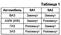
Setting the device to work in a particular class of cars is switches SA1 and SA2 in accordance with table. 1.
The operation of the device is illustrated by a transition graph shown in Fig. 3.
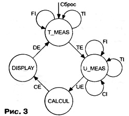
Count includes four tops-States corresponding to the modes:
- T_MEAS - (MEASURE TIME), the time measurement;
- U_MEAS - (MEASURE U) - voltage measurement;
- CALCUL - calculation mode in which the processing of measurement results;
- DISPLAY - the display mode of calculation results.
The transitions between the States shown by the graph edges that are caused by the following events:
- TI - (TIMER INTERRUPT) the interrupt from the timer IC;
- Fl - (FALLING INTERRUPT) the interrupt on the falling edge of the input signal;
- CI - COMPARE INTERRUPT) the interrupt from the built-in MCU comparator;
- THOSE, UE, CE, DE - the end of the measurement time, voltage, computing and display respectively.
After the power is reset MCU is initialized and the state TMEAS. First interruption is permitted only on the falling edge of the input signal (see Fig. 1), and in the presence of decay MK "grabs" it and starts to measure time the intervals. Then resolved timer interrupt. By counting the number of calculating the duration of the first time interval. Upon receipt of the input MK edge count value is stored and the measurement starts next interval. Likewise measured the length of all eight intervals, then the MC enters a state of voltage measurements U0(U_MEAS).
In this state, the MC generates the output R potential log. 1, whereby begins the formation of quasi-linear increasing voltage at the input with RSS by using the chain R3C6. Simultaneously start the timer MK at the time corresponding to level U0 = 0.2. Resolved timer interrupt and the comparator. If the first receives an interrupt from the comparator, it is identified the fact normal state contacts, as if from the timer, the contacts are unsatisfactory.
Further, the device enters the sleep mode CALCUL, when the calculated rotational speed of the crankshaft, the average value of USSC and the magnitude of deviation from this value. The latter two parameters are calculated only if the calculated frequency does not exceed 1000 min-1 (the nominal value of the measured USSC only at idle). After calculations, the program goes into DISPLAY
In this mode reads mounted switches SA1, SA2 type code of the vehicle, compares the computed values of USSC and irregularity of USSC with the relevant constants hardcoded in the EPROM, and the results of the comparison the signal plug a led. Then checked "getting" the current frequency of rotation of the crankshaft in the selected border and, if it is outside the set of values is activated sound corresponding tone. Next, the entire operating cycle is repeated.
The printout of the boot module of the program are shown in table. 2. Volume software code - 504 bytes.

(click to enlarge)
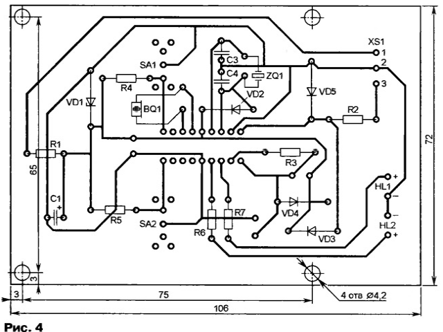
Parts of the device are placed on a printed circuit Board manufactured according to the drawing, is depicted in Fig. 4. The fee is designed to install the resistors MLT, the capacitors C50-35 (C1) and km (the rest), switches PD9-2 (SA1, SA2), three-celled pads XK.5-3. To connect microcontroller used 18-locular panel.
Establishing device begin with checking the voltage. To do this, not setting the microcontroller to turn on the power and measure the voltage across contact 5 of its panels. It should be not less than 4.5 In, otherwise the Zener diode VD1 should be replaced by another one with the right voltage stabilization. Then check the serviceability of the LEDs (alternately connect the cut wire pin 5 panel MK with its contacts 12 and 13).
Further, when the power is off set in the panel is programmed MK and connect the device to the terminal of a circuit breaker. If at power-up the device is not work, to pin 6 of the chip DD1 is connected to the oscilloscope (with input resistance not less than 10 MW), and test initiated whether the oscillator The MC. The absence of oscillations sinusoidal frequency of 8 MHz shows that the generator is not working. In this case, you need to check quartz the resonator ZQ1 and capacitors C3 and C4.
In car device is placed on the front panel in the driver's field of vision.
The functions of the device can significantly expand, instead of applying Z86E0208PEC modifications MK index 04, 08, pin-compatible and have a large memory resources programs and data.
Literature
Authors: M. Gladstein, M. Pounds, Rybinsk


