


")

This device is designed to control the drive motor side car mirror NISSAN BLUEBIRD made in Japan. This car provided as a separate adjustment of the position of the left and right side mirrors from the driver's seat and shared a switch that allows either press them to the body (close), or return to the operating position (open). In the mechanism drive each mirror has a node, stopping the electric motor when it is, turning reaches the stop.
My car refused node for controlling the drive of the left mirror. Right when this was regulated, opened and closed normally. Replacing building site I made and installed a homemade three electromagnetic relays.
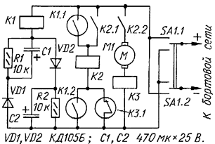
The switch control mirrors SA1 (see diagram) located on the instrument panel and has three fixed positions. In the middle position power mirrors not served, right arm of the switch is indicated on the instrument panel as a "mirror opened and left - closed". Depending on the situation arm switch changes the polarity of the supply voltage of the actuator motor and he accordingly rotates the mirror in either the "open" position, or - "closed".
If you put the switch SA1 in upper circuit position, as a result the flow of the charging current of the capacitor C2 for a short time triggered reed relay K1. This time depends on the capacitance and resistance of the winding of the relay; for the selected part types, it is 1…2 s. the Contacts K1.1 it includes the relay K2, which contacts K2.1 self-locking, and contacts K2.2 includes the motor M1 mirror actuator.
After charging of the capacitor C2 of relay K1 releases the anchor and the current through its winding will be determined mainly by the resistance of the resistor R2. The resistor R2 is chosen such that this current was less than the holding current of the relay.
After the motor will turn the mirror until it stops, the current through the motor winding sharply increased, which leads to triggering of a reed relay circuit. Contacts K3.1 it de-energizes relay K2, contacts K2.2 and opens the engine stops. Even if the switch SA1 in the extreme left position, the engine will be turned off and power consumption will not exceed 1 …2 mA.
If you now move the switch SA1 in the bottom in the diagram position, will change the polarity is supplied to the node voltage, but the order of work the device will remain the same. The only difference is that the relay K1 turns on the charging the same current of the capacitor C1 and the rotor of the motor will begin to rotate in the opposite side.
Resistors R1 and R2 are required for rapid discharge of the capacitors C1, C2 after turn off the power. The Contacts K1.2 prevent premature shutdown relay K2 a large inrush current of the motor flows through the relay coil K3 and resulting in short-term fires.
In the actuator used reed relays RGC (K1), passport BG.569.003-01, RES (K2), the performance of RF4.500.335-01. Relays K1 and K2 can be applied on any other the operating voltage of 12 V. the Main requirement for K2 - allowable current through the contacts shall not be less than the operating current of the motor. Relay K3 - improvised and is a coil of 15 - 20 turns any insulated wire diameter 0.6-0.8 mm, wound on a mandrel with a diameter of 5 mm (the length of the winding - 10…15 mm) and impregnated glue "super moment". Inside this coil installed the reed switch the Cams with the switching contacts of which used closed.
Establishing device consists in the selection of the number of turns in the coil reed relay K3. If too large a number of turns it will turn off the motor immediately after turning on. Consistently reducing the number of turns, achieve stable operation of the engine in normal operation and reliable off in extreme the provisions.
Author: Mikhail Fedotov, Seversk, Tomsk region.