


")

Schematic diagram of the device shown in the figure. The prefix consists of a timer DA1, switch delay transistors VT1, VT2, a transistor switch VT3, VT4 and oscillator elements DD1.1-DD1.3.
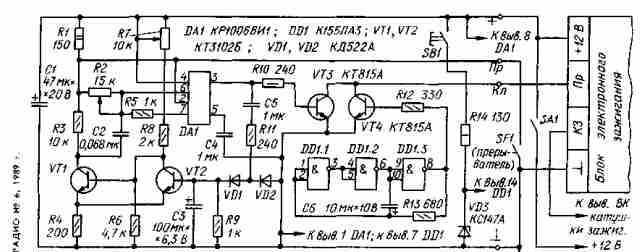
After turning on the power transistor VT2 will be closed. Mode transistor VT1 is selected so that when closed, the transistor VT2 it is open.
If the contacts of SF1 circuit breaker closed, the pins 2 and 6 of timer DA1 voltage close to zero, and at pin 3 signal corresponding to a high level. Under the action of this signal, the transistor VT3 is open, i.e. the state of the transistor switch is equivalent to the ignition unit is closed breaker contacts. For the first time after the contact opening at pin 2 of timer DA1 signal will be 1, and the pin 6-0, since the capacitor C2 is discharged. So at pin 3 of the timer signal of a high level will also continue, but until then, while increasing the voltage at pin 6 will not be equal to the voltage at pin 5. From that moment on pin 3 of the timer being set signal is low level and the transistor switch is closed.
Thus, by changing the resistance of timing chain R2C2, you can adjust the delay time of the closing transistor switch relative to the moment of opening of the breaker contacts. When indicated on the diagram of the part types zone of control delay is in the range of 0.03 to 0.8 msec.
With increasing shaft speed of the motor increases and the frequency responses of the breaker. The output signal of the timer,
repeating this frequency, passing through the rectifier device (VD1, VD2), charges the capacitor CP. At a certain frequency the voltage across the capacitor NW will be sufficient to trigger the switch delay. The transistor VT2 is opened and remains open, a VT1 - closes and disconnects the capacitor C2 from the common wire. Cremated-sort of breaks the chain. In this case, a transistor switch synchronous operation of the breaker contacts.
The resistor R7 allows you to change within 80…160 Hz frequency trip threshold delay. When switching to gasoline with an octane rating less than recommended, the delay time should be increased. The rotational speed of a crankshaft of the engine, which is not felt detonation, determined empirically, and is approximately 3000 min-1, which corresponds to the frequency responses of the circuit breaker 100 Hz.
The oscillator DD1.1-DD1.3 with an electronic ignition system creates a multi-spark in spark mode, which facilitates the starting of the cold engine. When you press the SB1 (only when running) ignition system generates instead of a single spark a series of sparks, following a frequency of about 50 Hz (-10° C).
In the device used fixed resistors MLT, variables SDR-4, the capacitor C2 Is K73-9. Transistors CTB can be replaced by the corresponding silicon structure with a gain current of at least 70, and CTA - CTA-CTV. Instead of chips 155 can be used KLA.
In the manufacture of consoles should pay special attention to the reliability of contact connections, the quality of soldering and protection from the external environment.
Authors: A. Kowalski, A. Frolov; Publication: N. Bolshakov, rf.atnn.ru