


")

If you install this small size of the device on the panel devices of your car, it will be able to control and digital display the scoreboard at your request up to seven very important parameters driving on the highway.
Described here is a variant of the device are designed for installation in "eight" and "nine" Volga car. To work on other vehicles in the device must to make larger or smaller changes. About finalizing trip computer MK-21093 to install on such cars as the Moskvich "Volga", the first the Vase model, we assume to tell in subsequent publications.
Trip computer MK-21093, produced by JSC Kursk Schetmash", designed for installation on gasoline automobiles VAZ-2108 and VAZ-2109. For new models VAZ-2114, VAZ-2115, the company produces a modification of this computer - MK-2114 - in the same dimensions, but with slightly different indications and a large number of functions. There's also a version MK-2112 other clearance for installation on automobiles VAZ-2110, VAZ-2111, VAZ-2112.
Trip computer MK-21093 measures and displays the seven parameters of motion car. At each moment the scoreboard shows the value of one parameter. Choose an interesting option by pressing. The list of controlled parameters and their values are presented in table.1.
Table 1
The controlled variable Designation button selecting The dimension of the parameter The limiting values of the parameter Discrete counts ("intercept") The current time of day "H" hour. min 00.00 23.59… 1 Current fuel consumption "IOM" l/100 km 0 62,5… 0,1 Average fuel consumption for the train "L/100" l/100 km 0…99,9 0,1 The total fuel consumption for the trip "L" l 0 624,9… 0,1 The mileage of the trip "Km" km 0…999,9 0,1 The average speed of the trip "KM/H" km/h 0…199,9 0,1 The trip "T" hour. min 00.00 99.59 staying… 1Operating range of the supply voltage of the computer - 10,8…15 V. To save information in the memory node it should not be less than 6 V. When the supply voltage is 13.5 the device consumes less than 20 mA when the display is off, and not more than 300 mA when enabled.
Chain light up at night control buttons consumes a current of about 100 mA.
Time for periodic updating of the information on the scoreboard (in addition to temporary settings) - 1,7 C. the Computer is operable at ambient temperatures from -40 to +60 ° C. When you turn on outdoor lighting car the brightness digital scoreboard the computer is reduced by 15…20 times and activated night light characters.
The value of the basic error of the computer when the power supply voltage of 13.5+0.2 V and the ambient temperature is 25+10 ° C current consumption does not exceed +(2 x 10⁻³ x Ax + 0,1), and for the rest (except time) - no more than +(0.5 x 10⁻³ x Ax + 0,1), where Ax is the induced value of the parameter.
The kit trip computer includes sensors fuel consumption and speed car. The first one is installed in the fuel line between the pump and the carburetor. This sensor has a conversion gain of 16,000 pulses per 1 liter of leaking gasoline.
Second install speedometer drive gear box has, the possibility of installing a flexible shaft for driving the mechanical speedometer is retained. The sensor produces 10 pulses per one revolution of the shaft of the speedometer (one meter of distance traveled). The "Niva" car has wheels increased diameter, and therefore the computer MK-21093 without the improvements will give unacceptable a large error.
Generally, the computer can be installed on any European car that has carbureted engine with a total volume of cylinders to 2.8 l and the actuator speedometer corresponding to the class A2 DIN 75532 (male thread fitting MH,5 and one rotation of the flexible shaft corresponds to one meter mileage).
Structurally, the computer consists of three main blocks (Fig. 1): processor digital display and keypad, each of which is assembled on a separate the circuit Board. All boards are placed in a plastic cover, on the front panel which has control buttons, LEDs and display of digital indicator. The supply voltage and the signals from the sensors are sent to the computer via pin the block connector.
The output signals of the sensors of fuel consumption and vehicle speed come on microcomputers DD1 through pulse shapers, each consisting of input filter (Z1 and Z2) and the comparator (U1 and U2). All nodes CPU eat from a regulated power supply connected to the vehicle network.
The code Converter and DD2 indicator HG1 display unit fed from voltage Converter power supply unit CPU. The voltage at the Converter is supplied from the ignition switch. A voltage regulator and Converter comprise a power supply unit G1 trip computer.
Control the mode of operation of the device and select the displayed setting circuit contacts S1-S10 keyboard. In the keyboard also includes a decoder and DD3 a set of LEDs HL1, which indicate the selected option and highlight the inscription on the panel in the dark.
After connecting the trip computer to the electrical system, it is necessary to perform initial preset, with the result that he goes into storage mode information. Ignition switches the device to the operating mode are included the digital display and led indicators on the front panel. Converter voltage provides power to the anode (15) and filament (~ 2.4 V) chains the indicator.
When the vehicle microcomputer in accordance with written on it the factory program processes the information contained in the signals, coming from the speed sensors and fuel consumption. The result of processing is supplied the indicator.
To obtain the desired information the driver presses the appropriate button on the keyboard, while the selected mode displays at the keypad joined led and digital display simultaneously displays the parameter value. When driving in the dark include Parking lights and the voltage from the vehicle electrical system is supplied to a part of the processor node A1 adjustment the brightness of the display indicator. As a result, the brightness of the scoreboard indicator decreases in 15…20 times, which makes for a more comfortable information read in low ambient light.
Schematic diagram of the routing processor of the computer shown in Fig. 2. All an external device connected to the processor via connector X1. With other blocks the processor is connected by thirty-six conductors, of which the first seventeen connected to the card display unit, and the remaining nineteen - pay - keyboard.
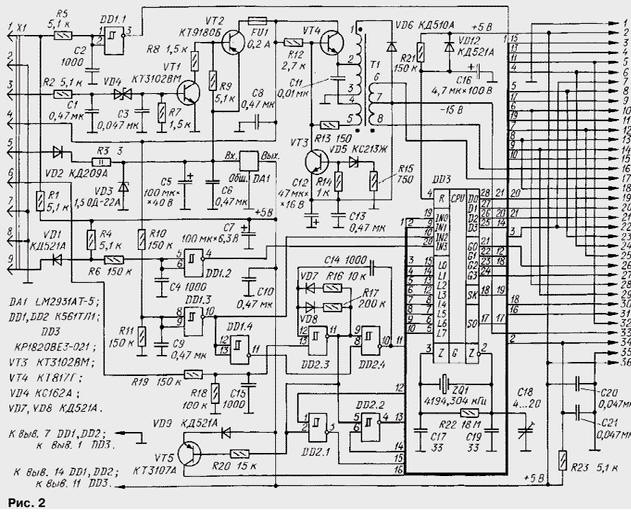
The voltage of pin 5 of connector X1 through diode VD2, protects the device from accidental reverse polarity and current limiting resistor R3 is supplied to integrated circuit voltage stabilizer DA1. Semiconductor limiter VD3 protects the input of the stabilizer from random spikes. The threshold limit - 35; in normal mode, the limiter is closed. To suppress variable component of the vehicle voltage is provided by the capacitors C5 and C6.
After switching on the ignition and the appearance of a voltage at pin 3 of connector X1 open the transistors VT1, VT2 and supply voltage (about 12 V) is supplied to the fuel gauge (pin 4) and stable Converter voltage, transistors VT4, VT3, the transformer T1 and working with frequency 50…60 kHz. With pins 1 and 3 of the transformer T1 is removed increased alternating voltage after rectification by diode VD6 (~15 V) is supplied to a keypad. AC filament (pulse) voltage to power fluorescent digital display comes with a separate winding (pins 6-8) of the transformer.
The pulsed output signal of the fuel flow from pin 1 of connector X1 through LPF R5C2 is input to the element DD1.1, having a rectangular top gear characteristics (Schmitt trigger). Resistor R1 is the load resistor of the sensor. The pulsed output signal of the speed sensor with contact 9 via connector X1 decoupling diode VD1 is supplied to load resistor R4 and through the LPF R6C4 - on the same input Schmitt trigger DD1.2.
The element DD1.3 assembled signal generator "on / off". While the ignition is not turned on and the transistor VT1 is closed, the input element DD1.3 - low level, the output is high. This high level signal "off" - holds microcomputers in the storage of information. Low level output item DD1.4 prohibits the operation of the generator on the elements of DD2.3, DD2.4. When the ignition is switched on the output element DD1.3 signal is generated for inclusion microcomputers in the form of a negative voltage drop.
Microcomputers made on the chip DD3. Her work built-in synchronized generator with quartz resonator ZQ1. The inputs of the microcomputer receives signals from shapers and buttons the control of the host keyboard.
The node control the brightness of the display is made according to the scheme of the oscillator pulses of the Schmitt trigger DD2.3, DD2.4. Frequency - 0,8…1,2 kHz when the duty cycle of the pulses 15…20. The voltage outdoor lighting car from pin 6 of connector X1 is supplied to the oscillator through the filter R19R18C15 and runs it. Output pulses of the generator (from the output of the element DD2.4) contact 5 output the feed pins on the processor are sent to the block display, and contact with a 32 - entry keypad.
Simultaneously, the pulses of the generator (from the output of the element DD2.3) together with signals from the outputs D3 and G1 microcomputer connected to the inputs of the elements DD2.1, DD2.2 and to the base of the transistor VT5. Output pulses of these elements also come on the block display (with contacts 3 and 4, respectively) to control the brightness individual elements of the scoreboard. Pulse sequence with a frequency oscillator brightness control taken from the collector of transistor VT5 (pin 31 of the comb), used in the keypad.
Schematic diagram of the display unit shown in Fig. 3. Information about numerical the value of each parameter of the movement generated by the microcomputer CPU, the output contacts 6-8, 10, 12-15 comes in binary code to the inputs the code converters DD1-DD4. From the output transducer signals in "semielemental" code supplied to the four-digit vacuum fluorescent the digital indicator HG1 operating in static mode.
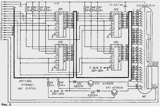
Once at the entrance To code converters will arrive pulse voltage (with contact 5), a constant voltage elements-the anodes becomes a sequence of pulses with a large duty cycle. As a result, the brightness the illumination elements included scoreboard decreases.
In Fig. 4 shows a block diagram of the keyboard. It consists of a button SB1-SB10 without fixation, decoder DD1, two groups of LEDs - HL1-HL7 and HL8-HL15. The LEDs of the first group indicate selectable modes of operation and the second highlight the lettering on the panel at night.
When you press a particular key on the keyboard to change the operating mode of the microcomputer, and it transmits the corresponding information on the display unit, and simultaneously the decoder DD1 keyboard - turns on one of the LEDs signaling the selected mode.
Just as this occurs in the display unit, here with the inclusion of marker lights impulse voltage generator with DD2.3, DD2.4 in the processor receives (from contact 32) inverted gate input SB decoder DD1 (pin. 4) keyboard - brightness LEDs HL1-HL7 reduced.
The brightness of illuminating LEDs HL8-HL15 controls the switching the transistor VT5 placed in the processor.
In block applied computer fixed resistors C2-33, C2-42V (R3 in CPU) oxide capacitors - C50-35, turn - CT-21B (C18 in processor), and the rest - K10-73-1B. The buttons in the keyboard - PCN-1 (permitted replacing them PCN-3).
Bipolar transistors CTB and CTG in the processor interchangeable transistors patterns of BSIT CPU and CPU respectively. Instead LM2931АТ-5 can be applied domestic stabilizer CREA. The LEDs in the keyboard used overseas in order to ensure maximum efficiency of the apparatus.
Trip computer MK-21093-protected certificate on the model and patent for an industrial design.
Authors: I. Nechaev, G. Radominski, Kursk