The described device is designed for installation on a motorcycle or motor scooter and designed for signaling to the driver on the health of the rear lamp red lantern in the dark or blowing out the lamp, resulting a traffic accident in the form of a rear-end collision.
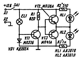
Schematic diagram of the device shown in the figure.

In series with the lamp tail light EL1 included diode VD1. When you turn on lamp toggle switch SA1, the lamp current passing through the diode, it creates a drop voltage, which is enough to unlock the transistor VT1 and enter it in the saturation. Thanks bases of both transistors VT2 and VT3 are attached to the shared bus. As a result, the transistor VT2 is locked, and VT3 opened, allowing its emitter current of the led glow green color HL1. Resistor R2 limits the current to the led to acceptable.
At burnout of the lamp, rear lamp, the current through the diode VD1 is missing, transistor VT1 is locked, whereby through a resistor R1, a current flows base transistor VT2, which he unlocked. Emitter current VT2 lit a red led HL2. Resistor R3 limits the current to the led. Thus HL1 led is not lit, as it shunted open transistor VT2.
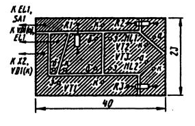
Printed circuit Board with the location of the circuit elements shown.

As transistors VT1 and VT2 can be used KT315, and as VT3 - KT361 with any letter index. The resistors R2 and R3 are selected when establishing to obtain a sufficient brightness of the LEDs.
Author: Y. Prokopcov


