


")

Every motorist knows how it is sometimes difficult to start the engine car on a winter morning after long Parking. However, relatively simple the device is powered by an AC voltage of 220 In substantially will facilitate this task.
The device consists of two parts (Fig. 1): one network power source (voltage 12-14); the second part is mounted in a motor compartment of the car. They are connected among themselves by means of a special connector.
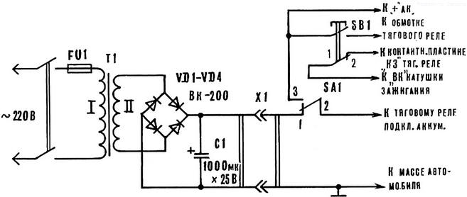
Fig. 1. A schematic diagram of a starting device.
In the engine compartment with bracket (Fig. 2) mounted Board on which mounted button SB1 (for "turning" and start), switch SA1 "battery - to-site and plug connector x 1 (for connecting to the source power).
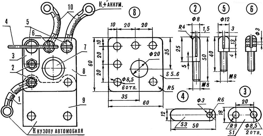
Fig. 2. Fee: 1, 10 - connecting cord, 2 - pin, 3 - jumper, 4 - arm switch, 5, 6 - contact switch, 7 - button, 8 - base, 9 - a fixing bracket.
The device provides a cranking of the crankshaft of the engine, and starting engine key in the ignition switch or button SB1 with the ignition on. When this from a power source energy is derived from the vehicle's battery.
The operation of the device consider the example of the car VAZ-2101. Linkable source to the electrical system via connector X1 (Fig. 1). The switch SA1 set to "network", and the source connected to 220 V. the Key ignition switched into the "off" position. Clicking the button SB1 implemented cranking of the crankshaft of the engine. However, the power from the battery through contacts button SB1 is fed to the traction relay. The power from the source through contacts 1-2 of switch SA1 is supplied to the traction relay and then through the closed contacts of the traction relay to the coil of the starter.
The engine is started with the ignition key, as usual. When the ignition is also run when the button SB1.
When using the device on the car "Moskvich-2140" and "Zaporozhets" the work shall contacts 1-2 buttons SB1, which prevent current from a source in the ignition system of the vehicle during operation of the traction relay. Wire, connecting the contact plate "K3" on the traction relay and clip "VK" coil the ignition must be turned off. The rest is as described above.
After finishing work, the device is disconnected from the network and from the vehicle, and the switch SA1 is set to "battery".
As the transformer T1 is used converted autotransformer Latr-1M. Alteration consists in the following. The winding is divided into two equal number of turns parts. The two halves are connected in parallel and donativum 45-50 turns of wire with a diameter of 1.5 mm, It will be a grid winding. After the laying of the insulation layer coil winding II, consisting of 15 turns of wire 40-50 mm2.
Diodes - VK-200 (or other designed for a rectified current of 200 A) installed on the textolite plate without radiators.
Connector X1 - homemade. Socket housing (Fig. 3) made of phenolic resin or other insulating material. In the housing is molded or glued socket (copper tube diameter 10x1 mm), to which is soldered connecting wires. The plug is mounted on the circuit Board (Fig. 2). Switch "battery - network improvised. His device is seen from the same drawing.
Fig. 3. Socket: 1 - connection cables, 2 - tube of 10 mm diameter, 3 - case
The wire, which is powered starter, cross section must be 30-40 mm and may be shorter. The presence of the capacitor C1 is not required.
Author: A. Vovk, S. Sharovka, Kharkov region