The purpose of this publication is to acquaint the readers with little known at the present time a group of devices - speech informants. The principle of their work is to playback voice messages recorded before, when exposed to the control inputs of the device. The production of speech of informants was made possible thanks to a wide the dissemination and accessibility of modern element base-digital circuits of low and medium degrees of integration of CMOS-series and inexpensive EPROM capacity of 2 Kbytes and above. The scope of the device is wide enough - stuffing for toys, room "talking" calls, solid-telephone answering machines, etc. Principles of digital sound processing are well described in [1], so they will not stop.
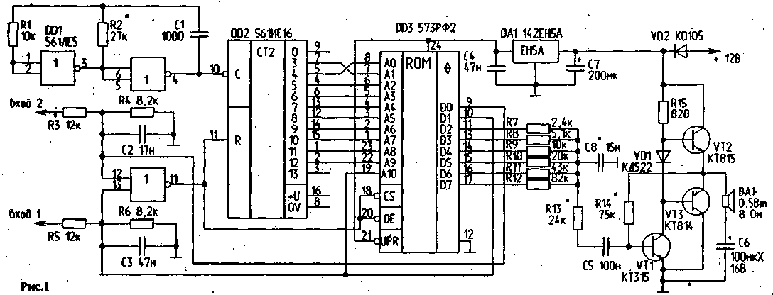
Readers are invited to automotive variant informant - speech indicator of the direction indicators accompanying the inclusion of lamps pointers words "left" and "right" - depending on the direction of rotation, called the author of "Dwarf" is invisible to the driver's assistant or instructor of a driving school (Fig. 1).

(click to enlarge)
The device operates as follows: after applying the power supply voltage +12 V starts the oscillator 2 elements DD1. On device inputs "1" and "2"- 0, so the counter DD2 blocked at input R. the EPROM Chip DD3 is in a state of "not selected", and its outputs in the high impedance state.
With the arrival of an input device voltage + 12 V connected group of lamps of indexes of turn signal S. the output DD1.3 is unlocked DD2 counter and selects EPROM DD3. Signals of logical "1" from outputs Q0 or Q1 EPROM, depending on what input you are running a device selected state is held until the arrival of a logical "0" at the outputs Q0 and Q1 EPROM at the same time. This should give the full message, even if the trigger level is+12 V at the inputs of "1" or "2" will be shot.
Actually the message is selected by a signal on input a10 EPROM Junior or senior half of the array. In the ranks Q2 Q7...EPROM recorded instantaneous value of the audio signal in binary code. Bust addresses is carried out with a frequency of about 1.9 kHz, resulting in the generation of two messages duration of about 0.5 s each.
Information from the outputs Q2 Q7...EPROM converted the simplest DAC in the form of a set of resistors with the ratio of the values of 1:2:4:8:16:32 the analog voice signal, which is input to the ULF on VT1 VT3 ...through a chain R13C5 that determines the sound quality and sound volume. Item C8 suppresses harmonics of the clock frequency and generates a treble. Stabilizer DA1 nourishes stable voltage +5 V circuits D01 DD3...
Details:
DD1 - CLE; instead DD2 KIA you can use 2 CIE with the change of the switching circuits; DD3 - CRF(5) or its equivalent 2716; DA1 - CREA (); diode VD1 - any low-power silicon; VD2 - on any current 300-500 mA; resistors - type MLT-0.25 tolerance of 5 %, it is only important perhaps more precisely (< 2 %) to ensure that specified above, the ratio of the values of the elements of the DAC in upper three bits (R7 R9...). Transistor VT1 - any low-power n-p-n-50...100; VT2 and VT3 can be replaced by GT and GT respectively. Capacitors C1 ...C5, C8 - type KM5. KM, K10-7 or similar; C6 and C7 - type K50-6, K50-16, C50-35. Dynamic head BA1 - 0?GDS-2-8 Ohms or 0.25 GDS-2 is 50 Ohms.
Adjustment devices start with ULF, setting the selection R44 voltage at the point equal To b V. the Selection of the diode VD1 achieve the absence of a "step" with a small signal. Then the selection of the R2 set the period of the clock signal generator 68. ..70 μs, controlling it with an oscilloscope. Feeding the input of "1" or "2" +12 V voltage, make sure to remove lockout level with the entrance DD2 R and the output of messages. The selection of the R2 set the required output rate of the message. Rl 3 - volume, C5 and C8 - bass and treble control, respectively, under the type of dynamic head and its acoustic design.
Author's variant assembled on a printed circuit Board H mm (Fig.2) and placed in the housing HH mm of aluminum alloy. M/scheme-mA DA1 and transistors VT2 and VT3 in heat sinks do not need, because in silent mode the device consumes less than 40 mA, and when issuing messages of up to 250 mA.
Encoding the ROM are shown in table.2 (see below file for the flash ROM). When using other parts, such as replacing the counter KIE note for the connection of 2 young bits of the counter and ROM, which made the "wise", i.e. the ROM addresses are selected in the following order: 0-2-1-3-4-6-5-7 -... that is done to simplify the trace of the PCB and respectively accounted for in the table of flash ROM.
Described the informant has the option of four messages (added m/scheme CLA and CRF - one PCs.) with you the PCB and firmware modification.
The size limit codogram a size of 2 Kbytes is not essential, just the capacity of the cheapest and most available EPROM. Codogram prepared by the author using a simple console to PC "Baltic" on the basis of high speed ADCS type CPU and software of our own design.
The firmware file of the ROM (2 KB)
Literature:
1. D. Lukyanov. The music of zeros and ones. Radio, 1985, No. 5,p.42-44; No. 6, p. 40-42; No. 8, p. P6-38; No. 9, p. 36-39.
Author: E. Zhukov, Bryansk oblast, Bryansk oblast; Publication: N. Bolshakov, rf.atnn.ru


