


")

Modern high requirements for environmental clean exhaust and fuel economy of motor vehicles, is feasible only when using engines with fuel injection and electronic control system. The number vehicles equipped with such systems, is growing in our country. However, the roads of Russia while most of them are of foreign make, but a lot of domestic cars. And according to the Volga automobile plant concept with 2001, all products will be manned exclusively engines electronically controlled fuel injection.
However, it should be noted that for all the merits of engines that are the speech, they are significant in the Russian context disadvantage. Even the simplest the fault cannot be identified and resolved without resorting to the car wash, because where there is a need for this expensive diagnostic equipment.
The author of the article, the device will allow the driver to decide many of the problems associated with the diagnosis of the fuel injection system. In addition, this unit duplicates and complements the speedometer, tachometer, pointer coolant temperature, voltmeter, econometr.
On most front wheel drive cars AVTOVAZ set engines with multipoint injection. The Central control device the injection system is dedicated controller. Most of the engines complement the M1 controller.5.4 Bosch. It handles coming from various sensors information and acts on the actuators, ensuring optimal operation of the engine. Find the output of any of parameters within the acceptable limits, the controller stores the fault code in internal non-volatile memory and includes display "Check Engine" on the instrument car panels.
Unfortunately, the car's regular means of various purposes you cannot read the error code and determine why lights up the scoreboard. This code and the controllable parameters of the M1 controller.5.4 issues only on special the connector to which the service station diagnostic plug equipment There are several types of diagnostic devices. But even one of the most simple - DST-2M - costs about $ 300. USA,, of course, prevents the widespread use of such devices the motorists.
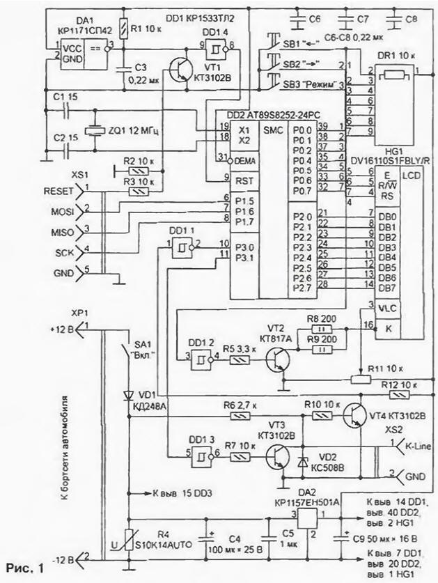
A schematic diagram of a diagnostic device which can be made independently, is shown in Fig. 1. The basis of this is a single-chip microcomputer AT89S8252-24PC Atmel (DD2). Every 100 MS, it queries the system engine control to the desired setting and outputs the value to liquid crystal display (LCD) HG1. Two-way communication with the controller Bosch M1.5.4 organized through the interface K-Line as per specification and IS09141 the Protocol of exchange of information Keyword2000. The clock frequency of the micro-computer (12 MHz) specifies the circuit consisting of a quartz resonator ZQ1 and capacitors C1, C2. From this frequency depends on the speed of data exchange via the serial port microcomputer, therefore, to use a crystal oscillator to a different frequency is invalid, the controller will not be possible.
Reliable starting of the microcomputer after the supply voltage is connected and a lock of her work in the case of lowering it provides chip CSP (DA1). She holds at pin 3 the level of the log. 0, while the supply voltage is less than 4.2 V. the Capacitor C3 regards endorsed a transition in the state log. 1 after the voltage exceeds the specified threshold. Full functional and design analog circuits CRS - PST529D company Mitsumi. With a different pin location also suitable DS1233-15 Dallas Semiconductor, functionality to the adm705 (Analog Devices), The MAX705 (Maxim). The latter also contains a watchdog timer that is designed to alarm is reset when the "freeze" of the microcomputer.
If we neglect the possible failure of the device as a result of "failures" voltage power chip DA1 can be omitted. The signal on reset will form a chain R1C3. In this case, it is desirable to increase the capacitance of the capacitor C3 1 UF and set parallel to the resistor R1 any low-diode, for example. KDA, cathode to +5 V.
To the pins of port P0 microcomputer connected buttons SB1-SB3, employees to manage device, and the control circuit of the LCD. Since the port has no internal load resistors, the formation level of the log. 1 at its conclusions by using external combined in resistor Assembly DR1. The findings of the port P2 is connected to the data bus of LCD.
Specified in the diagram LCD DV16110S1FBLY/R company Data Vision - one-line 16-character with built-in illumination. Instead another functionally similar, provided that its instruction set compatible with KS0066, and the character generator Russified. Suitable, for example, indicators HDM16116H-7 firms Hantronic, JA-16101 firms JE-AN Electronic, AC V company Ampire. Variable resistor R11 is used to adjust the contrast of characters on the LCD screen of the Microcomputer turns the LCD backlight with the key on the transistor VT2, which is mentioned in the scheme can KTA to apply any other transistor structures n-p-l with a valid collector current not less than 150 mA. The current in the circuit of the backlight limit connected in parallel resistors R8 and R9. Rated power of each of them - not less than 2 watts.
The host interface with a diagnostic circuit (K-Line) Bosch controller M1.5.4 transistors VT3 (transmit key) and VT4 (receiving key) triggers Schmitt DD1.1 and DD1.3. It converts the signal to a microcomputer with TTL voltage levels, 12 volt according to the specification IS09141 and back. To protect against possible surge is a Zener diode VD2.
Diagnostic device is fed from an onboard network of the car, which also there may be significant surges. Them protects R4 - special automotive varistor produced by S+M (Siemens Matsushita Components) SIOV S10K14AUTO whose resistance drops sharply with increasing voltage. It you can replace the Zener diode with a voltage stabilization 15…19 In, for example, CSA or CSA. Diode VD1 CDA protects against reverse polarity of the supply voltage. Instead, any other suitable diode with a valid direct current of at least 300 mA. With integral stabilizer DA2 CREA receive voltage 5 In for the supply of chips and LCD. The on-Board device blocking capacitors C6-C8 should be installed in the immediate vicinity of the power pins DA1, DD2 and HG1.
The control program of the diagnostic device consists of modules written in the languages of the Assembler and C compiler FSI (Franklin Software Inc). Program developed and compiled in an integrated environment PROVIEW32 V3.3.4 Build number 8.63. Assembler - A51 version 6.03.08, the C compiler version 6.11.4 With, the linker - version 4.08.06. Evaluation versions of these tools can be obtained on the company's website FSI at the address http://www.fsinc.com.
Codes's compiled code of the program is given in the table. Before installing the chip DD2 at the cost of the device it is recorded in the FLASH memory with versatile the programmer. This option is suitable if on Board for this chip provided by the panel. In such a case, the socket XS1 and the key transistor VT1 from the circuit device can be eliminated.


Note that devices operating on the car, all the conclusions circuits it is recommended to seal directly to the Board without transition panels. In conditions of high vibration, this measure excludes failures caused by short-term violations of the contact in the panels.
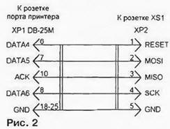
Of course, soldering programmed chip risky. But the micro-computer AT89S8252 allows you to enter in the program and after installing the Board. For this socket XS1 device connect cable with the socket of a personal printer port computer. Cable diagram shown in Fig. 2, its length is not more than 0.3 m. the computer to run a special program, for example, AEC ISP V1.00 AEC firms Electronics (http://www.aec-electronics.co.nz). Working with her is very simple, you need just select the menu item and follow the onscreen prompts.
Of course, before the programming of the microcomputer. diagnostic device should enable and check the correctness of its major units. Apply a voltage of 12 V at the power plug HR device I. closing the contacts of the switch SA1, check the presence of the stabilized voltage +5 V power pins of the chip. Then verify that a valid signal reset. After power on pin 9 of the microcomputer DD2 should be a single pulse of high level. In otherwise a faulty chip control voltage DA1.
Of the pins 18 and 19 DD2 must present the signal frequency of 12, and the output 30 (ALE) - 1 MHz. If the findings 18 and 19 there is a signal, and the output 30 it is not, is defective and must be replaced microcomputers. If there is no signal on one of the conclusions of 18 or 19, try to find the capacitance of the capacitors C1 and C2 or to exclude them. Sometimes requires replacement of the quartz resonator. Having stable operation of the internal oscillator, the microcomputer can be programmed.
After this operation, check for proper addressing program memory. On the output 29 (room) DD2 must be a constant high logic level, meaning the appeal to internal program memory.When there are the pulses should ensure that the level of the log. 1 at pin 31 of the microcomputer. If on the withdrawal of the room burst pulse appear periodically, this means that the address beyond the internal memory. Most likely, the microcomputer clean - the program is not listed.
After starting the control program initializes the serial port and a system timer of the microcomputer, and then initializes the LCD: the port P2 it outputs command codes, pulses followed by a logic high at the input of GE. Gave the command, the microcomputer switches the port P2 in the read mode and is waiting for the LCD signals readiness continue to provide pulses to the input of E. If the indicator is faulty, tone is not the program will "get stuck" waiting for him. This LCD must be replaced.
After initialization, the LCD screen will clear and it appears the phrase: "the Indicator M1.5.4". If you can see only black squares, you need a variable resistor R11 to adjust the contrast of the image. Simultaneously with the withdrawal saver microcomputer sets at pin 35 (P0.4) logic low - illuminated indicator.
After a pause at 3 p. the program tries to communicate with the controller Bosch Ml.5.4. At pin 11 of the microcomputer every 300 MS pulse appears low level duration 30 MS, 150 MS after it passed a few bytes of data at a speed 10400 bps. a Similar signal amplitude of 12 V must be on the pin 1 of the socket XS2 (chain K-Line), otherwise check the key on the transistor VT3. If everything is in order and the LCD displays the message "No connection", check diagnostic device is completed and it is ready to be connected to the control unit the fuel injection system.
In the relatively rare use of the device to nourish it from the nest cigarette lighter in the car. However, to turn the device on only after you have switching on the ignition. The fact that the Bosch controller M1.5.4 always starts their work attempts to establish communication with the immobilizer, feeding into the chain K-Line the appropriate commands. If the diagnostic line is already connected and working transmission diagnostic device, a collision occurs and the engine can to stall. This is a rare but possible situation. It was to exclude diagnostic device waits for 3 seconds before the first attempt to contact a domain controller.
Installing the instrument in constant operation, it is recommended to sue him the voltage of +12 In contact with 87 main relay fuel injection. It will make impossible to turn on the device when the ignition is off.
Socket XS2 is connected to the diagnostic block, as shown in Fig. 3.
On vehicles not equipped with immobilizer, connection information line (K-Line) the Bosch controller M1.5.4 with the contact M of the pad diagnosis, as a rule, ripped. To install it, needed a jumper between pins 9 and 18 pads for connecting the immobilizer. If the car had previously been diagnostics in the service station, this jumper is probably already there. Provided two modes of operation of the diagnostic device: displays the values of the selected the user parameter or fault codes with the possibility of erasing from the memory controller.
After enabling automatically set the display mode of the current value the option that was selected before turning off the device:
- throttle position, %;
- coolant temperature, C;
- the rotational speed of the crankshaft of the engine, min-1;
- given the speed at idle, min-1;
- the ignition timing, grad.;
- speed, km/h;
- the current position of the idling regulator, step;
- target position of the idling regulator, step;
- factor correction, multiplied by 100;
- voltage on-Board network;
- the pulse duration of the injection, MS;
- air flow rate, kg/h;
- hours of fuel consumption, l/h;
- track fuel consumption, l/100 km (only while moving);
- the symptom detection of detonation;
- tag lock the fuel supply;
- sign idling:
- characteristic power enrichment.
Parameter is selected with the arrow buttons (SB1, SB2).
To switch to the display of fault codes, press and release the button "Mode" (SB3). The LCD will display the number of codes stored in memory controller - If it is zero, the next time you press the button "mode" the device will return to the display settings. If fault codes are available, they can browse with the arrow buttons.
To exit the display mode codes without them briefly press the erase and release the button "Mode". To erase the codes from the memory controller, hold click neatby more than 2 s. After erasing the LCD should appear the number "zero" - a sign that in the controller memory codes left.
In the case of a connection failure with the Bosch controller M1.5.4 on the LCD diagnostic the instrument will display the message "No connection". After her resume automatically recover mode earlier.
Author: A. Alyokhin, Khimki, Moscow region.