


")

Descriptions of devices for lighting the display voltage level is already published on the pages of our magazine. What else can be added to published? It appears possible! Placed below the article confirms it: a real Amateur radio operator any problem in no hurry solved…
Voltmeter mounted on the dashboard of the car, allows you to quickly to control the level of voltage in its onboard, From such a device is not requires high resolution, but needed the ability to easily and quick legibility. The best way these conditions are met by discrete led indicator voltage. Such device has got very wide distribution and to assess the level of voltage and capacity (in sound amplifying equipment). Implement them as a rule, in two ways.
The first is described in detail in [1]. Its essence is that the line of LEDs connected to the source to be measured to a voltage through the resistive divider mnogobajtnye voltage. Here we have used the threshold properties of the LEDs, transistors, and the diodes. For simplicity of the indicator have to pay a fuzzy threshold ignition LEDs (which the author noted in [2]). A similar device in his time is sold in the form radiokonstruktor.
The second method is the application for inclusion of each individual led a comparator that compares the input signal with a model (as, for example, in [3]), Due to the high gain of the comparator, often running on the OS, thresholds on and off very clear, but for the indicator it takes a lot of chips. Quad opamps now more expensive, and one such the chip can operate only four LEDs.
Finally, we must mention the work (4), where we have used the principle of a / d conversion. This structure also many advantages, but still a bit too much details, and also uneconomical.
Voltmeter, offer you optimized in light of the foregoing - clear thresholds ignition LEDs obtained by using at least cheap, economical and widely available items. The principle of operation of the device is based on threshold properties of digital circuits.
The appliance (see diagram in Fig. 1) is a six-level indicator. For ease of use in the car the measurement interval is chosen to be 10…15 V with step in V. 1 And the interval, and the step can be easily modified.
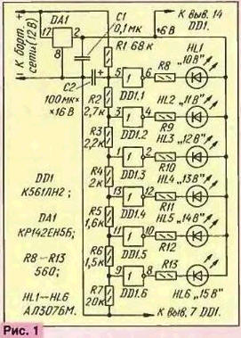
Threshold devices are six inverters DD1,1-DD1.6, each of which is a non-linear voltage amplifier with a large coefficient the gain. The threshold switching level of the inverter is approximately half voltage feeds crachami, they compare the input voltage with half of the supply voltage.
If the input voltage of the inverter exceeds a threshold level, at the output appears low voltage level. Therefore, the led that serves as a load the inverter will turn on output (input) current. When the output of inverters a high level, the LEDs are closed and deactivated.
From the outputs of the resistive divider R1-R7 to the input of the inverters is supplied the corresponding proportion of Board voltage. When you change side voltage proportional change in its share. The same voltage supply inverters and led line stable integrated stabilizer DA1. The values of resistors R1-R7 expect so., to get a step switch to 1 V.
The capacitor C2 together with the resistor R1 form a low-pass filter, suppresses transient voltage spikes that may occur, for example, during engine start. The capacitor C1, the integrated circuit manufacturer stabilizers recommends to improve their stability on a high frequency. Resistors R8-R13 limit the output current of the inverter.
How to calculate the resistors R1-R7? Despite the fact that at the input of the inverters DD1.1.-D1.6 includes polivalennetary that the input current is almost not consume, there is the so-called leakage current. This makes you choose the current through the divider a much larger total leakage current of all six inverters (not more than 6X10⁻⁵ µa). The minimum current through the divider will be at a minimum the induced voltage of 10 V.
We will set this current is 100 μa, which is about a million times more leakage current. Then the total resistance of the divider RD=R1+R2+RЗ+R4+R5+R6+R7 (in kiloomah if voltage in volts and current in milliamperes) must be equal to: Rd=Uвx min/Imin = 10V/0.1 mA = 100k.
Now calculate the resistance of each of resistors provided Uпор=u n and m/2, i.e. in the present case, the Uпор=3 V. When the input voltage is 15 V on the resistor R7 should fall 3, and the current through it (equal to the current through the entire divisor) D=UBX/Rd=15 V/100 kω= 0.15 mA=150 μa, Then the resistance of the resistor R7: R=Uпоp/D; R7=3/0.15 mA=20K.
At the input of the inverter DD1.5 3 In must be with an input voltage of 14 V. the Current through the divisor in this case D=14 V/100 kω=0,14 mA. Then the total resistance of the R6+R7=Uпоp/D=3/0,14-21,5 ohms.
Hence, R6=21,5-20=1.5 kOhm.
Similarly determine the resistance of the other resistors of the divider: R5=UпорхRд/Uвх-(R6+R7)-1,6 ohms; R4 2 kω, RЗ 2.2 kω, R2-2.7 ohms and, finally, R1=Rd-(R2+RЗ+R4+R5+R6+R7) = 70 ohms 68 ohms.
Generally, as is known, the threshold voltage of the elements of CMOS chips is the range from 1/3Uпит to 2/3Uпит. It is also known that are made in a single technological cycle on a single chip elements have one chip almost the same value of the switching threshold. Therefore, for accurate the installation "the beginning of the scale of the voltmeter quite a resistor R1 to replace series circuit of the trimpot with a calculated nominal value and with constant of value is two times less than estimated.
Temperature stability of the device is very high. When the temperature changes from -10 to +60 °C, the threshold is changed to a few hundredths of a volt. Integrated stabilizer DА1 also has a temperature stability is not worse 30 mV in the range 0…100 °C.
The output voltage DА1 should not oiti In less than 6, otherwise inverters will not be able to provide the necessary current through the LEDs. Inverters chips K561LN2 allow the output current to 8 mA. LEDs ALBM can be replaced by any other, counting the values of current-limiting resistors R8-R13. Capacitors the same can be anything for a rated voltage of not less than 10 V.
To establish assembled device connected to the output of the regulated source voltage, which will simulate the vehicle's electrical system. Setting output the voltage source of 10 V, and the resistance trimmer on high, rotate the engine until the led is switched on HL1. The other levels installed automatically.
Details of the voltmeter mounted on the circuit Board of foil fiberglass thickness of 1 mm. Drawing card is presented in Fig. 2. She designed for installation trimmer SDR-33, and the others - MLT-0,125, condenser C1 - KM, C2 - C50-35.
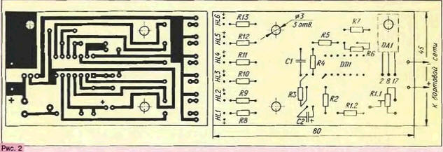
The fee attached to the bottom of a box of plastic with two screws M2,5 tubular racks and another the same, which simultaneously presses the chip to the Board DA1. Note that this chip installed plastic (not metal) face to the Board. Between the chip package and the printed circuit Board is also installed tubular hour, but shorter.
The findings of the LEDs before installation is bent at 90 degrees, so that their the optical axis was parallel to the plane of the Board. The buildings of the LEDs should to extend beyond the edge of the Board and at the final Assembly of the device to go in holes drilled in the side of the box.
The stability of the stabilizer and the entire device in whole will be even higher, if the input of the circuit (between the pin. 8 and 17) to connect a capacitor with a capacitance of 0.1 MK. In order to protect the regulator from random spikes in the on-Board network, the amplitude of which can to reach 80 00 V. in parallel with this capacitor should be connected one - oxide. He must have a capacity of at least 1000 μf and voltage ratings 25 V. This capacitor blagopriyat will have an impact on the work of radio and PA automobile equipment.
Literature
Author: O. Klevtsov, Dnepropetrovsk, Ukraine