Modern vehicles are equipped with lots of information and index instruments and signal lamps intended to control the efficiency of their core systems. However, the resulting visual information, on the one hand, requires the driver distraction from road traffic control and not comfortable enough and may not always be observed at the time. This problem particularly relevant for drivers with little driving experience, and the consequences can be severe. For example not observed at the time of indicator engine temperature is too hot can lead to its failure and, consequently, to large financial costs. No less can be unpleasant and undetected failures other parts of the vehicle such as brake and lubricating system, generator, rear signal lights, etc.
We offer our readers a "talking" on-Board system control (BSC) is intended for use in domestic and imported cars and gives information about detected faults in speech form. Messages are issued to a male or female voice (depending on used software and firmware "speech" ROM), and the speech quality corresponds to "phone" on the classification Windows Sound System. The list of messages generated by the system shown in the table. N a Condition of the issuance of the message Sentence alarm number CBP messages 1 the Temperature of the engine 2 engine Overheating more than 98 2 Lower level brake Failure of the brake system 2 Noah fluid (triggering of cabin depressurization braking system) 3, the Voltage No battery charging 2 less than 11 In 4 a Voltage failure of the voltage regulator - 2 more than 15 tion In 5 Low oil pressure Emergency oil pressure 2 the rotational speed of Kaleva- La 900 rpm 6 who is completely open - Closed air barrier - 1 stuffy flap carbura - ka Thor (included the "leak") when the engine temperature With more than 80 7 circuit failure lamp Failure brake 2 brake 8 circuit failure lamp Failure marker signal 2 tail lights 9 circuit failure lamp Failure signal 2 reverse reversing lights 10 After ignition Happy trails 1 all controlled systems normal Multiple instances of this device more than a year operated on cars of different brands and showed high reliability and efficiency.

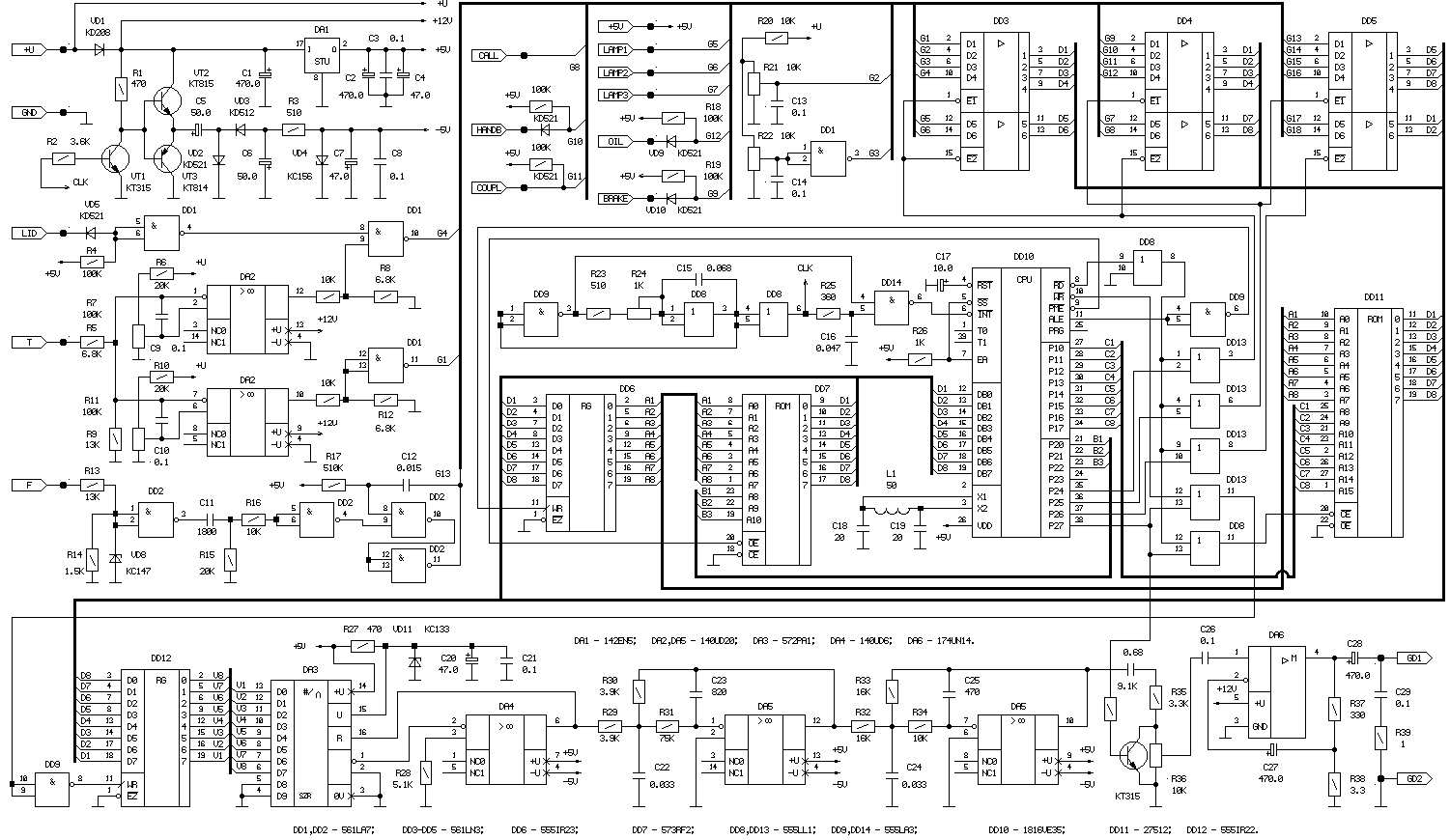
Fig.1 (click to enlarge)
The device (Fig.1) is implemented on the basis of the single-chip microcomputer CRUE. Chip DD6 performs the functions of the driver the address bus, and DD7 - external program memory. Port P1 OMMM used DD10 for the formation of a higher address "speech" ROM DD11, which contains digitized and in a certain way compressed speech information. Significant bits of port P2 of OMMM are used for addressing the ROM programs DD7, and the upper bits of this port, together with the IP DD13 and DD8.4 for select external devices: ROM speech DD11, switch input DD3-DD5 and register the sound path DD12. Logic elements DD8.1, DD8.2, DD9.1, DD9.4 is provided with a pulse generator frequency 7 kHz is used as the clock in the speech output.
The front-end portion of the circuit, providing interface switch data DD3-DD5 with the electrical system of the car and bringing the input signals to TTL levels, implemented on the IC DD1, DD2 and DA2. When this operational amplifier DA2.1, DA2.2 carry out the comparison of the signal of the temperature sensor with setpoint set by resistors R7 and R11, on the chip DD2 implemented the normalized pulse shaper the duration of the input pulse plugs, and the IC DD1 work as the level Converter and threshold elements.
As is seen in Fig.1 schematic of input lines 18 switch data DD3-DD5 used to enter information only 10. The remaining inputs are partly used as a utility when configuring the device and partly as a reserve for additional sensors and system development.
The audio path includes a digital-to-analog Converter IP DA3 and DA4, the Butterworth filter 4 order of frequency slice 3 kHz op amps DA5.1, DA5.2 and amplifier low frequency DA6.
Power source BSC performed on the integral stabilizer DA1, forming a voltage of +5 V, and the transistors VT1-VT3, which together with elements VD2-VD4 and C5, C6 provide a polarity reversal and stabilization of the supply voltage of -5 V. as the control pulses inverter polarity signal is used CLK generated by the clock generator output speech.
The device configuration is implemented with the help of trimming resistors:
R7 - tuning the temperature at which issued the phrase "Closed air flap";
R11 - set temperature for the issuance of the phrase "engine Overheating";
R21 - setting the voltage for the phrase "Not charging the battery";
R22 - setting the voltage for the phrase "Failure of the voltage regulator";
R24 - adjusts the clock issuing of speech;
R36 - adjusts the volume level.
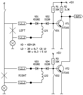
In Fig.2 is a schematic diagram of one of three identical channel block control the efficiency of the bulbs in the rear lights. Given the parallel connection of the same lamps for independence control each circuit diagram of the car being finalized by introducing a diode junction lamps using VD1, VD3. After such a processing unit, the control performance of both lamp when it is on and off.

Fig.2
As long as the voltage on the lamp is not filed, the elements R1, VD2, LD1 and R3, VD4, LD2 together with the filaments of the respective lamps form a voltage divider. Since the resistance of the filaments of the lamps are very small, the voltage drop across them is negligible, the transistors VT1 and VT2 closed and the output node is present a logical "1". In the event of breakage the circuit of any of the lamps corresponding to the transistor opens and the output node is formed by a logical "0" is a sign of failure of the lamp. Included in the state of the lamps, i.e. when they are energized from the electrical system, control of their health by using sensors current. The sensors are reed switches KD with wound windings LD. The latter is connected in series with the controlled lamps, so when flowing over them current contacts of reed switches are closed, sunterra base-emitter junction of transistors. Transistors VT1, VT2 are in the closed state, and the output node in the logical state "1". Failure of any of the lamp current through the winding of the respective sensor does not leak, the contacts of the reed switch opens, opens the corresponding transistor and the output node is changed to the opposite.
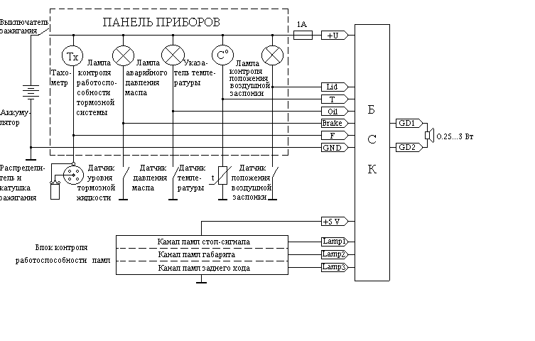
The BSC is connected to the electrical system of the vehicle in accordance with the scheme shown in Fig.3, and operates as follows.

Fig.3
After the filing of the device supply voltage when the ignition is switched on, the scan begins dealing with the staffing of vehicle sensors and outputs of the unit control the efficiency of the lamps. If within 5 seconds on any of the input lines of the BSC is not committed is a sign of failure, scanning sensors is interrupted and the device goes to the issuance of the phrase "Happy journey", by selecting the digitized information from the ROM speech, after which he again returned to the sensors. In the event of the subsequent operation of the vehicle on one or more input lines BSC sign of failure, the device will likewise give the appropriate phrase alarm. Thus to ensure the reliability of the device operation and protection against false positives, the active level on input lines BSC perceived as a sign of failure only if it is present on the line continuously for 3 seconds.
In most cases, the program provides a double repetition of the phrase to improve the reliability of its perception. In addition, with the same purpose each phrase is preceded by a tone audible alarm, attracting the attention of the driver and prepares it to receive information.
Structurally, the device is in the form of two blocks: the block of BSK, placed in the vehicle under the dashboard, and the block control the efficiency of the lamps installed in the area of the rear lights.
Author: S. Suckow; Publication: N. Bolshakov, rf.atnn.ru


