Many cars are still years of production have a simple variable speed operation of the wiper (two positions - "fast/slow"). More comfortable in the proposed unit. It ensures continuous operation of the wiper within 1 ...4 1...3 cycle brushes). Pause between cycles can be adjusted from 0 to 20 with a variable resistor mounted on the front panel. A similar block is described in [1], but it has a significant disadvantage - depending on the on-Board voltage of the vehicle, the time intervals of the device change markedly. The proposed device is devoid of this shortcoming and contains fewer parts.
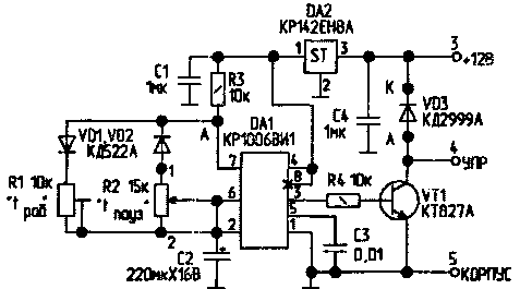
Consider the work of the unit (Fig.1). The timing Assembly is built on the timer DA1. The possibilities of this IC is described in [2]. The timer generates a pulse signal with adjustable pulse duration trimmer R1 (motor windshield wipers work) and pauses the variable resistor R2 (the wiper motor does not work).

Fig.1
When the unit is switched on by the regular switch on the dashboard of the car through R3, VD1 and R1 C2 begins to charge. Immediately after applying the voltage, the timer output DA1 is set high voltage level. Transistor VT1 is opened and the power supply circuit of the wiper motor is energised. Internal circuit of the timer is constructed so that after the charging of the capacitor C2 to 2/3 IP, the voltage at the output of the timer decreases to almost zero, and the transistor VT1 is closed. The engine also stops after returning the brush to its original state.
Pin 7 of the timer is the open collector output of the transistor. Resistor R3 is the load of this transistor. Its emitter is connected to ground. When the timer switches with internal trigger IC to the base of this n-p-n transistor comes a positive signal, and it opens. As a result at point a voltage close to zero. The capacitor C2 begins to discharge through R2, VD2 and transistor circuits. When the voltage on the capacitor is reduced to 1/3 of the supply voltage, the timer is switched to one state at the output (pin 3), and closes the internal transistor. The C2 capacitor again begins to charge.
The power to the timer and time-setting circuits stable chip DA2 to temporary block parameters did not depend on on-Board voltage of the vehicle. Capacitors C1, C4) to ensure proper operation of this IC, preventing the excitation. The capacitor NW reduces the effect of noise on the duration of the generated pulses. Diode VD3 is necessary to protect the transistor VT1 from the EMF of self-induction motor winding that occurs when switching. Resistor R4 sets the base current of the transistor VT1 at 50...70 mA. The load capacity of output 3 IC DA1 - 100 mA, so that in the absence of the compound transistor VT1 it is possible to replace the electromagnetic relay. In this case, the diode VD3 is not required.
Details
Transistor VT1 can be any letter. Diodes VD1, VD2-any silicon compact. Diode VD3 can be taken from the series KD, KD, KD with any letter index. The capacitor C2 is preferably of the series K52, K53. It is durable capacitors with low leakage currents, but since they usually have a small capacitance, the capacitor C2 can be composed of two, including them in parallel. The remaining capacitors - all-ceramic compact. Fixed resistors - types C2-33, MLT; AC - SDR-30A, trimming SDR-386 or SDR-d.
Design
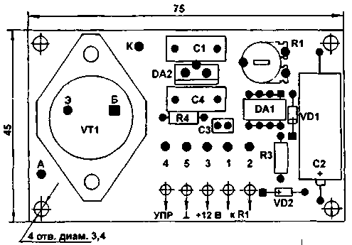
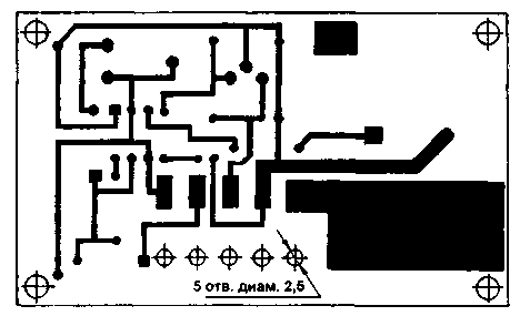
The unit is assembled on a printed circuit Board from one-sided foil fiberglass. The location details and the drawing Board is shown in Fig.2 and 3. On the PCB there are 4 mounting holes and the holes for fixing the wires coming to the control unit. It is recommended to make the wires from the unit length of 7 cm, strip them at a length of about 2 cm, and then to connect with automotive staffing wires by the method of twisting, followed by isolation. Diode VD3 should be placed on the transistor VT1 insulating side of its body to the transistor.

Fig.2

Fig.3
The unit is installed on the vehicle under the dash. Thereafter, a trimming resistor R1 expose the number of cycles of operation of the brushes from 1 to 3.
Literature
1. P. Oleynik Integral timer in the control unit wiper. Radio, 1988, N12, P. 25.
2. Gutnikov B. C. Integrated electronics in the measuring devices. - Moscow: Energoatomizdat, 1988.
Author: A. Rudenko, Kharkov; Publication: N. Bolshakov, rf.atnn.ru


