


")

The engine control system consists of a control subsystem of the distributed fuel supply (fuel injection) and the engine management ignition. Both subsystems are managed by El. a control unit ( controller ) and ensure efficiency of the engine.
The system includes (see Fig.1) fuel tank, al. fuel pump, fuel pump relay, fuel filter, distributor (battery) fuel, fur. a pressure regulator fuel injectors ( one for each cylinder of the engine ), the sensor mass air flow (MAF) sensor, throttle position (TPS), feedback potentiometer (potentiometer), knock sensor (KS) sensor, coolant temperature (CTS), sensor vehicle speed (ACD), the crankshaft position sensor (ДПSW), al. the control unit, ignition module, battery, ignition switch, control lamp "CHECK ENGINE", the fan of system of cooling of the engine (SOD), idle control (IAC) and may include the adsorber, immobilizer, air conditioning.
The block diagram of the control system
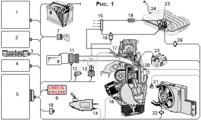
1. The conditioning module 14. The speed sensor of the vehicle 2. The immobilizer 15. The fuel distributor (ramp) 3. Diagnostic connector 16. The regulator of pressure of fuel 4. Main relay 17. The fuel injection valve (injector) 5. The controller 18. The crankshaft position sensor 6. The battery 19. Fuel filter 7. The ignition switch 20. Knock sensor 8. Air filter 21. The coolant temperature sensor 9. Lamp "CHECK ENGINE" 22. The relay of inclusion of the fan 10. WITH potentiometer 23. The ignition module 11. Air flow meter 24. The fuel tank 12. Position sensor etc. damper 25. The fuel pump 13. Idling speed controller 26. Relay-fuel pump
The engine fuel control operates as follows:
Fuel El. the pump ( through the fuel filter ) delivers fuel from the fuel tank to the ramp ( the distributor ) of fuel which is a regulator of pressure of fuel supplied to the injectors. Diaphragm pressure regulator sets the fuel pressure level in the system of about 300 MPa and returns excess fuel to the fuel tank through the fuel return line. In addition, the fuel pressure in the system depends on the vacuum in the intake tract, which is supplied to the pressure regulator. On the diaphragm overflow valve pressure regulator fuel on one side affects the fuel pressure and the spring pressure and the pressure of the intake air. This ensures optimal fuel pressure in the system is directly dependent on throttle position and engine load.
Fuel injectors are controlled by the controller and provide simultaneous flow of fuel into the intake manifold of each cylinder of the engine during each revolution of the crankshaft. The number of arriving in the combustion chamber fuel is proportional to the opening time of the injectors. The controller, in turn, regulates this time specifying its input signals from sensors installed on your engine. The time of filing of the control signal to the injectors, the controller detects the signal of the crankshaft position sensor.
In the start mode of the motor controller switches to asynchronous mode control the injectors until the engine speed at 400 rpm.
Fuel supply to the combustion chamber terminates in the purge mode of the engine (throttle is opened more than 75% , and the rotation of the crankshaft when it is less than 400 rpm) and may briefly stop mode engine braking depending on coolant temperature, engine speed, vehicle speed and throttle opening.
The enrichment of the fuel mixture in the modes increased engine load and acceleration controller produces increasing the opening time of the injectors, regulating it according to the signals of the sensor, throttle position sensor and mass air flow, taking into account the vehicle speed, the signals of the speed sensor.
The electronic control unit controls the voltage in the vehicle electrical system and a significant reduction increases the opening time of the injectors, compensating (low voltage) delayed the inclusion of Electromechanical valves injectors.
In all modes of engine operation according to the signals of the sensors, throttle position and mass air flow controller determines the number entering the engine air and regulates the supply of fuel injectors to provide the required composition of the fuel mixture. When warming up a cold engine and at idle, the controller controls the operation of the idling regulator, and depending on the load and the temperature of the engine provides the speed of the crankshaft at the required level. With the rapid closing of the throttle when driving the controller increases the flow of air control idling. Thus depleted fuel mixture for reducing exhaust emissions.
Management performs ignition controller according to the signals of the crankshaft position sensor and given the current mode of engine operation according to the signals of other sensors.
The electronic control unit (controller) is a microprocessor-based system with permanent non-volatile storage device (ROM), non-volatile reprogrammable memory device (EPROM) and random access memory device (RAM) to store data only in the presence of the supply voltage. In the ROM data stored program microprocessor operation and table parameters of the motor. For intermediate values, the microprocessor uses the RAM. The controller controls the actuators of the injection of fuel (ignition, injectors, etc.) and in addition, carries out a diagnosis of the operation of the sensors. If a failure is detected, the controller ignites the lamp "CHECK ENGINE" and stores in RAM error code that can be read by a multitester or indicated by the lamp "CHECK ENGINE" in scan diagnosis codes.
Connection diagram elements
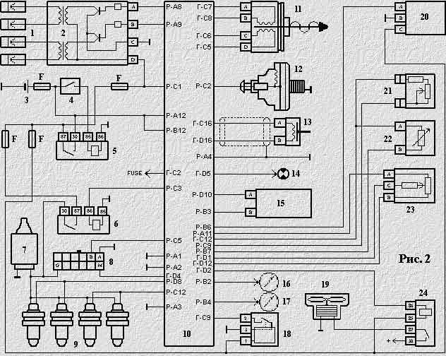
1. The spark plug 14. Lamp "CHECK ENGINE" 2. The ignition module 15. The conditioning module 3. The battery 16. Tachometer 4. The ignition switch 17. Speedometer 5. Main relay 18. Speed sensor 6. The relay of the fuel pump 19. Radiator fan O. W. 7. The fuel pump 20. Sensor air flow 8. Diagnostic connector 21. WITH potentiometer 9. Fuel injectors 22. The thermode Oh.fluids 10. The controller 23. Position sensor etc. damper 11. Idling speed controller 24. Fan relay 12. Knock sensor Fuse F. 13. The crankshaft position sensor FUSE. To the onboard computer
Scan error codes and diagnostics system "January 4"
Sensor mass air flow (MAF)
Sensor vehicle speed (ACD)
CO-Potentiometer feedback (SOP)
Sensor, throttle position (TPS)
The crankshaft position sensor (ДПSW)
Idle control (IAC)
The throttle body (cdhs)
Publication: www.cxem.net