


")

Most "Western" firms have settled long - Board computer controls all the processes in the engine and controls them. In the domestic automotive industry this issue is not properly addressed and, as a result, the characteristic of the advance angle formed by the centrifugal Governor mounted on almost all domestic cars, coincides with the optimal characteristic at best 2-3 points (Fig 1) At some sites it may differ from the optimum by more than 30%, and long-term operation of the vehicle, this value grows.
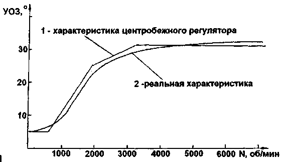
Fig.1
First it reacted to autoradiographically. Thanks to them, there was quite a simple circuit proofreaders ignition the basis of their work is based on the principle of forming an adjustable time interval which is delayed sparking Since the advance angle and the specified time interval at different rotation speeds LW - values are not proportional, with this correction speeds LW advance angle of the engine increases so that harm more than good Therefore some authors off correction at engine speeds above LW 2000 2500 Rev/min.
The next step was the creation of the correctors, the principle of which was laid formation directly regulated POPS Despite the fact that this method is more progressive in it, as in the previous, there is one drawback - they both form a delay that is added to the initially incorrect characterization of the generated centrifugal Governor So the next step is to abandon the use of a centrifugal regulator and the creation of shapers optimum advance angle on the basis of the ROM containing the codes for the optimal allocation of advance angle depending on often you spins LW One of these devices is described below.
In operation of the device based on the principle by which the optimum advance angle characteristic over the entire range of engine operation (from 600 to 6000 rpm) is divided into 256 sections At each site is fixed advance angle value is encoded in the range from 0 to 256 and is recorded in ROM 256 bytes will be offset specified characteristics on the vertical (smooth) and horizontal (speed) axis which gives the opportunity to adapt it for different engine types and different brands of gasoline.
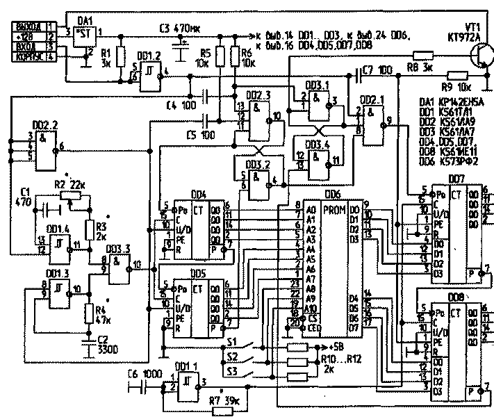
The operation of the circuit
The generator circuit is shown in figure 2.
His work can again be divided into three stages
- the measurement of the angular frequency of rotation LW - formation phase advance angle adjustable (vertical adjustment)
- the stage of formation of the optimum ignition advance angle .
The first phase begins when you receive a logic high from the magnetic sensor to the input device While integrating chain C4 R6 momentum on the leading edge which starts the generator(G1) assembled on DD1 3
The pulses of frequency f1 through D3 3 is input to the cascade-connected counters DD4, DD5 running on the increase and accumulate information on the duration of the input pulse At the completion of the input pulse on duration (that is, about the importance of momentum LW) from the outputs DD4 DD5 in binary code is supplied to address inputs of the ROM In the ROM in accordance with the received address code is generated time delay corresponding to the optimum ignition advance angle (measured rpm value LW) This code is in binary form is written in parallel into registers counters DD7, DD8 pulse generated by the chain C7 R9 Simultaneously, the generator G1 is blocked generator G2 collected on DD1 4 begins to produce pulses of frequency f2 and counters DD4 DD5 starting to work on reducing accounts so it begins the second phase.
It should be noted that at the first stage in starting mode of the engine (rpm LW below 600 rpm) results in an overflow of counters DD4 DD5 While at pin 7 of the counter DD5 formed a short negative pulse, the switching trigger DD2 3, DD3 2 (T1), which in turn blocks the counters DD4, DD5 recorded in their maximum information (code 255) In this state diagram is the end of the input pulse through the decay of which integrates chain C7 R9 is formed of the negative pulse that writes code 255 in DD7 DD8 Simultaneously through a chain C5 R5 reverse trigger switch T1 and allowed to work on subtraction counters DD4 DD5.
When counters D4, D5 count to zero, at pin 7 of the counter DD5 is formed by a short negative pulse, the switching trigger T1, which in turn blocks the counters DD4, DD5 and allows the DD7, DD8. At this second stage begins and ends with the third.
Counters DD7, DD8 recorded at the end of the first phase information is used for subtraction. The enable signal of the trigger T1 flowing through the element DD2.1, they begin to perceive the pulses produced by the generator GP, collected on DD1.1, and when the countdown reaches zero, producing a negative pulse at pin 7 DD8), switching the trigger on DD3.1, DD3.4 (T2), which in turn, via DD2.1 blocks the counters DD7, DD8, and through VT1 generates a delayed output signal.
Timing diagram of the operation of the circuit shown in Fig.3.

Fig.3
Characteristic points of the diagrams:
About - the beginning of a positive input pulse, the resolution of counters DD4, DD5 an increment until the end of the input pulse or until they overflow;
1 (only for starting the engine) - the contents of the counters DD4, DD5 reached a maximum (255); lock DD4, DD5 before the end of the input pulse;
2 - write content DD4, DD6 through the code Converter DD6 in DD7, DD8; end G1; reset lock DD4, DD5 and start their work from G2 to subtraction;
3 - contents DD4, DD5 reached zero, and their work is blocked; a DD7, DD8;
4 - content DD7, DD8 reached zero, and their work is blocked; on the collector VT1, a signal is generated on the leading edge of which occurs the ignition;
5 - upper dead point of the respective piston;
6 - reset lock DD4, DD5; beginning of the next cycle.
For setting up the device it is necessary to know two parameters: -the length of pulses issued by a magnetic sensor, expressed in angular units (degrees) relative to the period of rotation LW; - optimum advance angle characteristic (dependence on rpm LW). Because this feature is specific to different cars, you can proceed in two ways.
The first method.
Using available address bits used ROM (A8, A9, a10), dial-up switches S1 …S3 (Fig.2) captured him in 8 variants of the characteristics obtained by the displacement along the horizontal axis after every 50… 100 rpm 2 baseline characteristics (Fig.1), which is typical for many cars. Thereafter, operating the switches S1…S3 controller and R2, in the course of numerous trials, subjective symptoms, determine the most suitable one. It should be noted that when switching to gasoline with a lower octane rating is necessary to move to a characteristic that is left from the original, and Vice versa. Finding the most suitable characteristics, it is advisable to rewrite the ROM, again shifting the received characteristic, but with a smaller step, for example after 20…30 rpm, the choice of the required grade of gasoline switches S1…S3.
The disadvantages of this scheme include the low stability of the generators. To increase the generators need to use resistors with a minimum of TCS and capacitors with zero TKE (group IGOS). For this reason, the device is better to place in the vehicle where the temperature difference is smaller than under the hood.
To reduce noise on the power pins of each chip is advisable to install ceramic capacitors of 0.1 μf, and the long commutation relations on the input circuit DD1.2 - a simple low pass filter with a time constant of about 0.01 MS (for example R=30 kω, C=300 pF). In addition, in some instances counters with matching fronts counting and control signals, as well as during the transition of accounts from one cascade to another arise malfunctions. To eliminate this phenomenon it is necessary to set the load capacitance of 100…200 pF between pins 6 DD2, 7 DD8 and common cord.
The driver is installed in the gap between the magnetic rpm sensor camshaft and electronic ignition system. When you set the shutter driver staffing centrifugal regulator need to be locked in a position corresponding to the maximum rotation speed SW.
Additionally, for the organization of the anti-theft function, it is convenient to use a resistor R2 with a circuit breaker that is connected in series with the regulator. Upon opening the switch contacts are in the end position R2, the engine will not start. For these purposes, you can also apply a combination lock, the output of which must be connected to pin 9 counters DD4, DD5. If the correct code on the above conclusions should do a low logic level.
Authors: V. Petik, V. Chemeris; Publication: N. Bolshakov, rf.atnn.ru