Such a call can be set in the apartment instead of the usual electric. And then when you press the button at the front door of the apartment filled with the sounds of popular tunes that you choose for yourself in advance and will program.
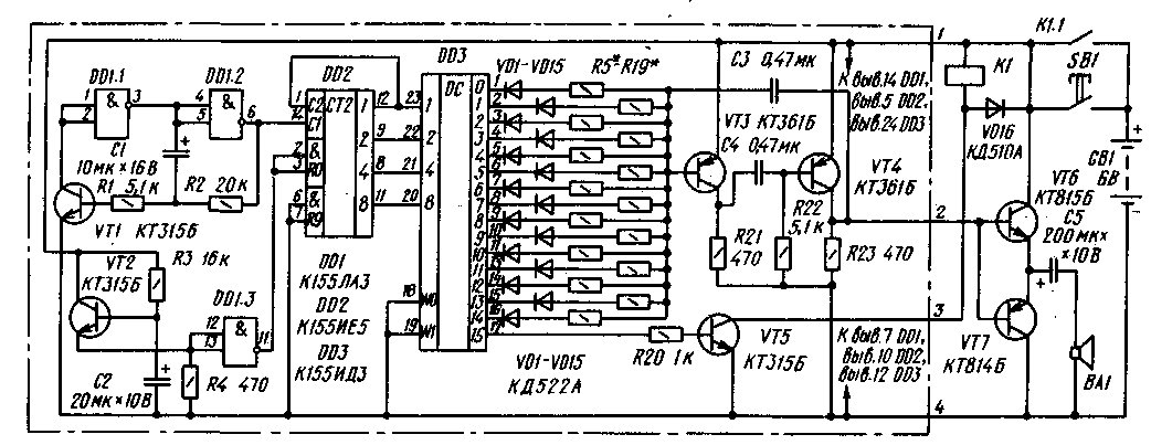
In the call (Fig. 1) used three chips and seven transistors. On the elements DD1.1, DD1.2 and the transistor VT1 made clock generator for generating pulses with a duration of approximately 0.5 s. They arrive at the counter DD2, the outputs of which are connected to the decoder DD3.

Fig.1 (click to enlarge)
In turn, the fifteen outputs of the decoder are connected through decoupling diodes VD1-VD15 and resistors R5-R19 to the acoustic frequency generator, assembled on the circuit of the multivibrator transistors VT3, VT4. With the generator signal is fed to the power amplifier is assembled on the transistor VT6, VT7. Load amplifier is the dynamic head of BA1. As soon as you press the button SB1, the call power source GB1. At pin 17 of decoder. as in other output pins, there is a logic level 1. Opens the electronic key transistor VT5, relay K1. The Contacts K1.1 relay locks the button - it can be released.
After pressing the button the meter is switched on immediately, but after a time required to switch the relay. For this purpose in the call entered the node delay is performed on the transistor VT2 and the element DD1.3. The length of the delay depends on the resistance of the resistor R3 and the capacitance of the capacitor C2.
Only after enabling the counter to the inputs of the decoder will start to receive signals in binary code. In this case the outputs are set to "move" the logic 0 level from the upper circuit output to the bottom, connecting the common wire (minus power supply) or that customizados resistor of the generator of sound frequency. Dynamic head is able to emit sound corresponding scale. When the level of logic 0 will appear at the output (pin 17), the electronic key will close the relay from coming in, the call will turn off.
In this design you can use resistors MLT-0,125 or MLT-0,25, oxide capacitors K50-6. the remaining capacitors - km-6. Diodes - any silicon. Dynamic head - capacity 0.25 to 1 watt and voice coil resistance 5...8 Ohms. Relay - reed or any other, triggered at voltages up to 4 V and consumes a current less than 100 mA (less than current consumption, the longer it will serve as a power source). Power source - four elements 343 which are connected in series.
The details of the nodes circled in the diagram, the dash-dotted line, are mounted on printed circuit Board (Fig. 2) from one-sided foil fiberglass 1.5 mm thick. Resistors R5-R19 solder in the process of establishing the call.
Cost is attached inside the case of a subscriber of a speaker or other suitable dimensions of the housing. Ibid. set the power source, relay, diode VD16 and capacitor C5. The output transistors are attached to the body near PCB screws M3, and the dynamic head is mounted on the front wall.
The establishment of call to begin with checking the operation of the clock generator. To the exit of the element DD1.2 connect the oscilloscope and observe the pulses of the generator - they should be approximately 0.5 C. If necessary, this value can be changed by selection of resistor R2 and capacitor C1.
Next, check the operation of the counter and decoder serial appearance at the outputs of decoder logic 0 level - it also helps the oscilloscope. The selection of resistor R5 (the others are not available) first set the tone to the desired tone, and then adjust other tones to the selection of appropriate resistors. At this stage it is convenient to "lengthen" clock pulse, temporarily connecting in parallel to another capacitor C1, the capacitance 20 50... UF. Also, instead of resistors R5 - R19 better to include a variable or adjustable, the resulting resistance is then measured and permanent solder a resistor of the same or maybe close resistance.
If in some place of the melody to be a pause, a resistor and a decoupling diode to the corresponding output of the decoder is not being served.
To call worked fine, check the condition of the elements of the power source and with a significant (more than 1) the voltage drop of the source under load, when the call is on, replace the elements.
Author: G. Shulgin, Moscow; Publication: N. Bolshakov, rf.atnn.ru


