On the pages of magazines you can meet a lot of diagrams and descriptions of musical calls, but they all have one drawback - the number of tones is limited (not more than 16), so they quickly remembered and bored. Offer the device is capable of synthesizing up to 120 melodies that are played sequentially with each press zvonkova button.
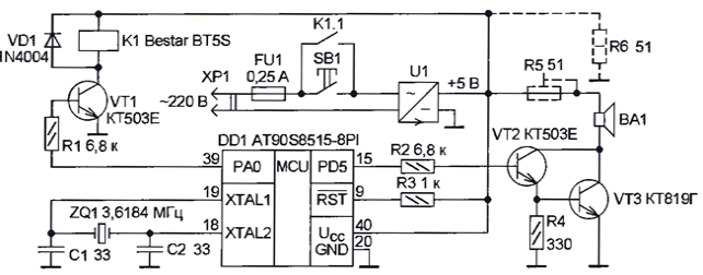
Schematic diagram of the call shown in the figure. It is based on microcontroller AT90S8515-8PI ATMEL. When pressing the bell button SB 1 included feeding device, starts the program stored in the memory microcontroller, and at pin 39 (RAO) there is a voltage log. 1. In the result opens the transistor VT1, relay K1 and To their contacts 1.1 blocks the call button.

For the formation of oscillations 3H is used, the timer of the microcontroller and the mode of its work on switching pin PD5 (to get the desired sound frequency the frequency of operation of the timer has to be multiplied by two). The signal taken from this the output is amplified composite transistor VT2VT3 in the collector circuit of which included dynamic head of BA1. To adjust the volume in series with you can include a trimming resistor R5 (shown in dashed line).
After playing the melody, the program writes to non-volatile memory (EEPROM) microcontroller the pointer to the next tune, a high level on it the output 39 is replaced low and the relay breaks the power circuit until you press the button SB1.
Ringtones taken from Melody Player program for Motorola (located in archive mp4m.rar). To convert the tunes in assembler view is written program motcvt (located in the archive motcvt.gags). Using it is easy change/add/remove any tune. When run on the command line indicate file name with tunes from mp4m and the name under which it is necessary to record the result file (for example, mel.inc).
The source code for the microcontroller are in the archive zvonok.rar, highlights commented. When using quartz resonator another frequency is required in the string .equ fsck = 3618400 file zvonok.asm change the value of the frequency (3618400) actually used (in Hertz). Everything else recalculate the assembler. The program is written and debugged using AVRStudio 4.0 Build 181.
Power source U1 is stable with any output voltage 5 V (can to use and the battery is composed of battery cells or batteries). Instead BESTAR BT-5S permissible use any relay with a voltage less than 4.5 V and contacts designed for switching the mains voltage of 220 V.
In the process of debugging the device detected that the contents of non-volatile the data memory of the microcontroller may be damaged if after turning off the supply voltage drops to 0 slowly (over 10 MS). The fact is that when you smooth it lowering the microcontroller some time continues to work, and this may cause incorrect decoding, and (or) sample commands that, in turn, capable of provoking an unauthorized entry in EEPROM. To prevent damage to memory contents can be used the so-called detector downgrade supply voltage (domestic CROP or its foreign equivalent PST529), with the fall of the supply voltage is below a specified threshold issues the Reset signal, thereby stopping the operation of the microcontroller. The author for this goals used the resistor R6 is connected to the output of the power source as additional load (shown by a dotted line).
The project files
Author: M. Bielecki, Ufa


