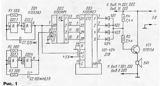
About melodious calls was described in the "Radio", for example, in [1, 2]. Offer their own version of a similar design (Fig.1) containing a relatively little elements and using the laws of probability theory.

On the chip DD1 made two generators: one clock (on the GTI the elements DD1.3, DD1.4), the frequency of the other ("high" - on elements DD1.1, DD1.2) is divided into an arbitrary natural number from 1 to 16 - the counter-divider DD3. The signal is "high frequency" of the oscillator is input to "+1" (the bill for the increase) of the counting trigger chip DD3. At the end of the account there has been a parallel load register with DD2. The result is a new the division ratio of the frequency.
The shift register DD2 works in this case sequential download (from input D0). In this mode it is transferred to the input of the low S level. The outputs 1-3 code is kept constant during a cycle, and then is changed to another from the decay clock pulse coming from the GTI to the input of C1 register DD2. Be a shift bits by bits of the register and load the next random bits per input DO serial download. Therefore, "high-frequency" alternator is not only asking, but also serves as a source random number stored subsequently at the outputs of the register.
From the output of the decoder diodes VD1-VD4 pulse oscillations of audio frequency amplified current of the transistor VT1 and converted into sound dynamic head BA1. The duty cycle of the oscillations is directly proportional to the index, which divides the frequency of the GTI. The result is a sound signal with a rich harmonic spectrum.
The device is indicated in the diagram, it is permissible to use chip series C, K555. Transistor can be any of series CT, KT815, CT, dynamic head - 0.25 to 1 W with a voice coil impedance of 8-16 Ohms. Diodes - any other germanium, low-power, capacitor - rated for a voltage below 6 V, the resistors - MLT-0,125, MLT-0,25.
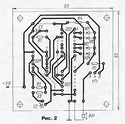
Parts of the device, in addition to the dynamic head, mounted on a printed circuit Board (Fig. 2) of one-sided foil fiberglass, which together with the head is placed in a prepared or improvised housing. Dotted lines in the drawing Board-marked wire (in isolation) jumper.

The supply voltage fed to the device via the bell button. Source power can be a battery, composed of three series-connected galvanic cell voltage of 1.5 V. a Few worst - network the supply unit must always be plugged in.
Literature
Author: M. Boyko, Kineshma Ivanovo region.


