


")

With the advent in the homes of private lobbies, deaf or double metal doors there is a problem with the definition of the trigger housing call. Coming up to the door, the guest presses the button for the apartment call… and hears nothing. Waiting then he presses the button the response is silence, and no one opens the door. Whether owners not home, or simply does not work call. If you enter a lighted the tripping call, guest, realizing that the call works, won't be nervous and banging on the door.
Another case where someone in the house resting, and "vociferous" call this rest it will spoil. But silent light indicator (of course, in a place where it be sure to notice) anything to anyone "not spoil". Yes, and people with weakened hearing it will help most Importantly, do not then forget to turn the ringer.
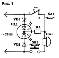
In Fig.1 shows a simple diagram indicating operation of residential call. In her based on the publications [1, 2]. As can be seen from the diagram, the call HA1 can work when closed the switch SA1. When this green led is on G matrix HL1. To disable the call is disconnected SA1. HL1 led goes off. If now to press the call button SB1, it is in these moments illuminate the red led R matrix HL1. The call is not audible, but the alarm about his work there.
A modified scheme of the display unit shown in Fig.2. Here, the switch SA1 for high resistance shunted by a resistor R2. and in series with the resistor R1 included low-power Zener diode VD3. In the initial state SA1 ("On") R2 is short-circuited and the operation of the circuit is not involved. No significant impact and the Zener diode VD3 (the green led G led matrix HL1).
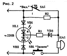
If SA1 open, the green G led will remain lit, but the brightness of his glow dramatically reduced. This is due to a significant increase in the value of resistance in its circuit (ballast resistors are R1 and R2). When pressed button SB1 glow green led matrix HL1 almost stops, but bright lights red led R this two-color led. The Zener diode VD3 provides almost complete cessation of the illumination of the green crystal HL1. This increases the purity of the visible color emission of the red led matrix in this mode.
The advantage of the circuits in Fig.1 and 2 is that in the open state of the button SB1 current through the coil of the call HA1 does not leak. When you press the button SB1 current is determined by the resistance of the coil of the call alternating current ("silent" mode the current through the coil of the call is very small).
Instead of two colour led HL1, you can use two normal colored LEDs, e.g., red ALBM and green ALUM (or even two single color).
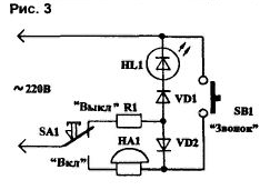
Diagram of the call will be further facilitated, if SA1 with a group of contacts on the switch (Fig.3). When SA1 is in the "On" position, call HA1 - able readiness, and HL1 led is not lit. When you click on SB1 coil the call is receiving AC mains voltage, and it rings. In the position SA1 "Off." (as in Fig.3) HL1 led is lit. R1 resistor - ballast (tomographically). Call HA1 energized, but in moments of pressing the button SB1 parallel to the chain VD1-HL1 connects the diode VD2, and led HL1 in moments of pressing the call button goes out.
Select the type of LEDs is determined by the capabilities and taste. The Resistor R1 limits the current to the led. therefore, for most cases, the resistance can be about 82… 150 ohms (should be selected experimentally). Power dissipation of this resistor is 1…2 W so that it is substantially not heated. The resistance R2 for the circuit in Fig.2 may be somewhat less than R1. Diodes VD1, VD2 for all considered schemes are protective for LEDs, so must withstand the peak voltage. It is advisable to use widespread diodes type 1 N4007 or KD105B. The Zener diode VD3 scheme in Fig.2 can be of almost any type, for example, KSA.
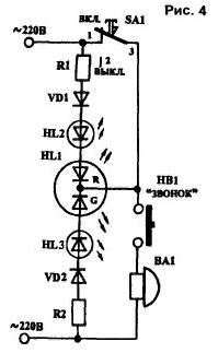
To indicate a call in the apartment is the easiest way to turn on the LEDs, for example, DBM, ALUM, consistently with LEDs R and G Assembly HL1, as is done in Fig.4.
Enough inside to indicate the work of the call using a single led (Fig.5).
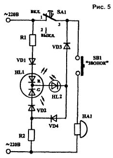
In this scheme simultaneously with red led R Assembly HL1 through the diode VD4 receives power, the led HL2 and glows with a little brightness. When call HA1 led HL2 glows brightly in standby mode - weak, and when you click button SB1 brightness HL2 increases.
LEDs outdoor display is usually installed in the housing of the doorbell.
Literature
Author: E. L. Yakovlev, Uzhgorod, Ukraine