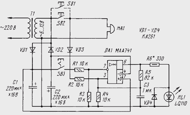
This device allows you to confirm that you visited in your absence? In HL1 light-emitting diode glows after someone used bell housing.

When you press the call button SB2 (see picture) to the non-inverting input of op-amp via diode VD3 serves the positive half of the voltage. As a result, the output of op-amp you receive a positive voltage relative to the common point of inclusion capacitors C1 and C2. Due to the positive feedback through resistor R3 the device enters a steady state in which its output will be the voltage close to the positive supply voltage. Resistor R6 limits the current through the led in the range of up to 15 mA. For voltage the secondary winding of the power transformer 6 In the resistance value of this the resistor shown in the diagram, and at a voltage of 12 V should be increased to 820 Ohm.
To bring the device to its original state is possible by briefly pressing on button SB3. In this case, to the inverting input of op-amp is connected to the positive the voltage of the capacitor C1 and the OS goes into a state of negative the voltage at the output. Diode VD4 protects the led from HL1 excess return voltage.
Device to use chip CUD, rectifier diodes CDB and led ALA.
Authors: M. Arendas, M. Rucka


