


")

Unusual sounds and sound effects, obtained with the help of simple electronic consoles on CMOS chips, capable of impressing readers.
Scheme of one of these consoles, is presented in figure 1, was born in the process various experiments with popular CMOS chip CLA (DD1).
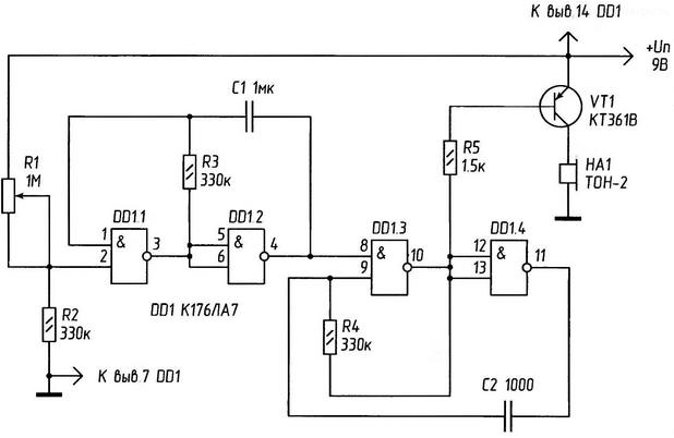
Fig. 1. Electrical diagram "weird" sound effects.
This scheme implements a cascade of sound effects, especially from the animal world. Depending on the position of the engine variable resistor that is installed on the input of the circuit, you can get almost real to the ear sounds: "the sound of a frog", "Nightingale trill", "meow cat", "the lowing of a bull" and many others. Even various human inarticulate combinations of sounds like a drunk cheers, and others.
As is known, the nominal voltage of such circuits - 9 V. However, practice to achieve real results may deliberate understatement voltage to 4.5-5 V. In this scheme remains operational. Instead chip 176 series in this embodiment, it is appropriate to use it more widespread analogue series C (C, C).
Fluctuations in the sound emitter BA1 are served from the output of the intermediate logical schema element.
Consider the operation of the device in the "wrong" diet - at a voltage of 5 V. as a power source you can use the batteries from the elements (e.g., three AAA batteries connected in series) or stable the main power source is installed at the output of the filter-oxide the capacitor has a capacitance of 500 µf with voltage not less than 12 V.
On the elements DD1.1 and DD1.2 assembled pulse generator triggered "tall the voltage level on pin 1 DD1.1. Pulse frequency sound generator frequency (AF), the application of the above RC-element, the output DD1.2 will be 2-2,5 kHz. The output signal of the first oscillator controls the frequency of the second (collected on the elements DD1.3 and DD1.4). However, if the "off" pulses with output 11 of the element DD1.4-no effect. One of the entrances of the closure is controlled through the resistor R5. Both generator working in close conjunction with each friend, snowslides and realizing the dependence on the input voltage in unpredictable packs of pulses at the output.
With the exit of the element DD1.3, the pulses arrive at the simplest amplifier current transistor VT1 and, repeatedly amplified and reproduced by the system BA1.
Details
As VT1 will fit any low-power silicon transistor p-n-p conductivity, including KT361 with any letter index. Instead of the radiator BA1 they can use the phone earpiece TESLA or Patriotic primer DAMS-4M with the resistance of the winding 180-250 Ohms. If necessary, gain audio volume is necessary to Supplement the basic diagram of a power amplifier and to apply the dynamic head of the resistance winding 8-50 Ohms.
All the resistors and capacitors are advised to apply those on the scheme with tolerance of not more than 20% in the first elements (resistors) and 5-10% second (capacitors). Resistors-type MLT of 0.25 or 0.125, capacitors-type MBM, km and others, with a slight tolerance to the influence of ambient temperature on them capacity.
The par value of resistor R1 IOM 1-variable linear characteristic resistance.
If you want to stay on any one favourite effect, for example "the cackle of geese" - it is necessary to achieve this effect very slow rotation of the engine , then disconnect the power supply and desoldering a variable resistor from the circuit and, measure the resistance, set the circuit constant of the resistor is the same par.
With proper installation and proper details of the device begins to work (make sounds) immediately.
In this embodiment, sound effects (frequency and interaction of generators) depend on the supply voltage. When you raise the voltage more than 5 V, for safety input of the first element DD1.1, must be connected in the gap of the conductor between the upper circuit contact R1 and the positive pole power limiting resistor 50 to 80 ohms.
The device I have in the house is used for games with Pets of the dog's training.
Figure 2 shows a diagram of an oscillator is a variable frequency audio (CC).
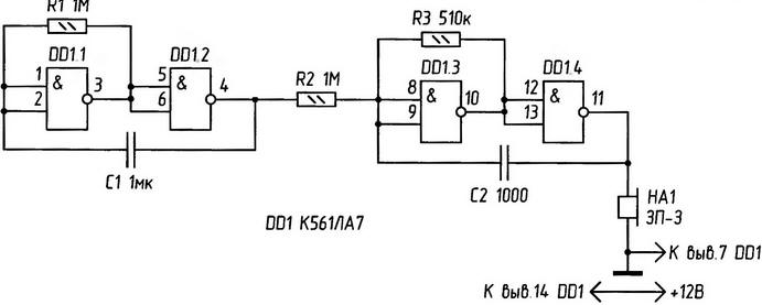
Fig.2. The electrical circuit of the audio frequency generator
The generator AF is implemented in logic elements of the chip CLA. Two first elements of the assembled low-frequency generator. He controls the frequency high-frequency oscillations of the generator on the elements DD1.3 and DD1.4. From this it turns out that the circuit operates at two frequencies alternately. On hearing mixed the vibrations are perceived as "trill".
A sound emitter is a piezoelectric earpiece SN-(SN-2, SN-W, SN-18 or similar) or a high-resistance telephone earpiece with winding resistance more than 1600 Ohms.
Property health CMOS chip C series in a wide range the supplies used in the audio circuit of figure 3.
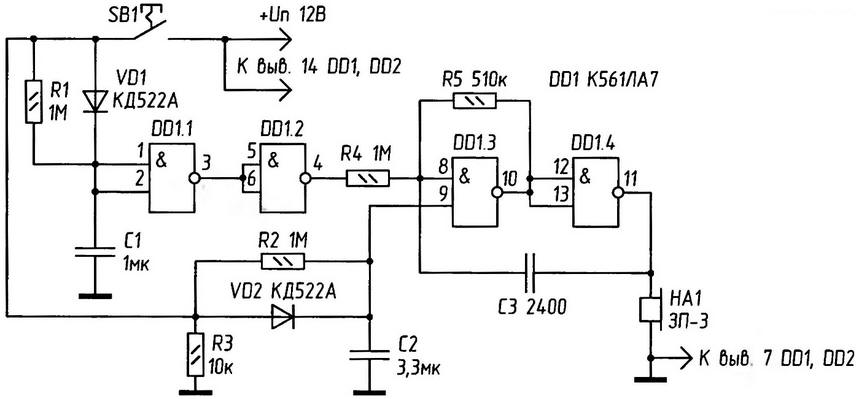
Fig.3. Electrical self-oscillating circuit of the generator.
Oscillating oscillator on the chip K561J1A7 (logic elements DD1.1 and DD1.2-Fig.). Gets the voltage from the control circuit (Fig. 36), consisting of RC-charging chains and source follower FET VT1.
When you press the button SB1, the capacitor circuit of the transistor gate charge fast and then slowly discharged. Source follower has a very large resistance and work the charging circuit is almost not affected. The output VT1 "repeats" input voltage and current sufficient to power the elements chip.
The output of the generator (the connection point with a sound emitter) is formed oscillations with decreasing amplitude until, until the voltage becomes less than acceptable (+3 V for chipset series C). After this fluctuation crack. The oscillation frequency is selected to approximately 800 Hz. It depends and can be adjusted by the capacitor C1. When its output signal AF for sound radiator or amplifier, you can hear the sounds of "cats meowing".
The scheme presented in figure 4, allows you to play the sounds cuckoo.
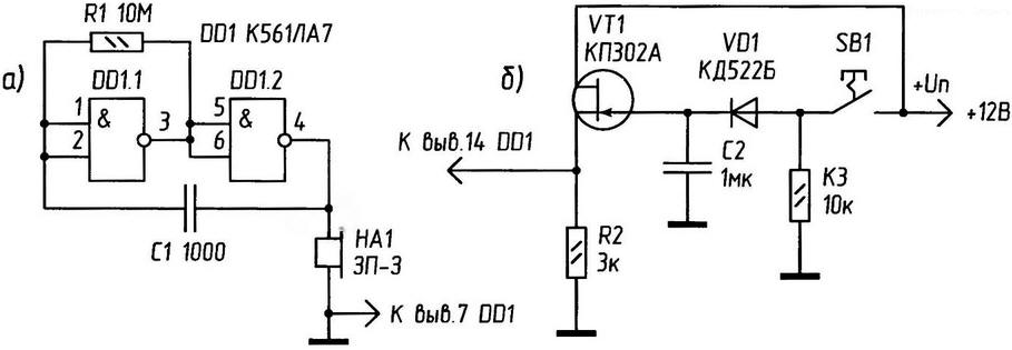
Fig. 4. Electric circuit device with simulated "cuckoo".
When pressing the button S1, the capacitors C1 and C2 is quickly charged (C1 through the diode VD1) to the supply voltage. The discharge time constant of about 1 for C1, for C2 - 2 C. discharge Voltage S1 at the two inverters DD1 chip is converted to a rectangular pulse with a duration of about 1 s, which through a resistor R4 modulates the oscillator frequency on the chip DD2 and one inverter circuits DD1. During the pulse duration oscillator frequency in the range of 400-500 Hz, with his absence - approximately 300 Hz.
The discharge voltage of C2 is fed to the input element And (DD2) and allows the generator for approximately 2 s. as a result, the output of the circuit is obtained dual-frequency impulse.
Schemes are used in consumer devices for attracting attention custom audible indication to what is happening to electronic processes.