


")

Many hams are building all kinds of model airplanes, ships, trains, cars and other equipment. However, to illustrate them with their prototypes it is desirable to "voice" that will give them even greater the attractiveness. Recall, for example, sounded like a train. First heard gradually increasing the noise of a train, then near the station he gives whistle when they are approaching, and if you stay, noisy releases steam with a sound, resembling "poof-poof-poof". Before sending sounds bell station, and the locomotive gives a farewell whistle, going on a journey.
The proposed description is sufficiently simple synthesizer sound effects for model a passenger train with a steam locomotive. Block diagram of the synthesizer is shown in figure 1. It consists of several independent blocks: generator "chug, whistle generator, generator, ringing bells, mixer, amplifier CB with loudspeaker. Description last block is not given.
Fig. 1. Block diagram of the synthesizer sound: 1 - block "steam" 2 - block "whistle", 3 - "the bell", 4 - mixer, 5 - USC, 6 - the speakerphone.
Unit 1. As can be seen from the diagram (Fig. 2), the base-emitter junction of the transistor VT1 works in breakdown mode and creates a continuous "white" noise (spike). This signal is amplified by the transistor VT2, operating near threshold operation. Timer DA1 creates pulses with a frequency determined by the capacitance of the capacitor C1 and the resistance of the resistor R3. Changing the resistance R3 can be slowed down or to accelerate the "chug" of the engine within a wide range. The pulses output from the timer served on the electronic key VT3. Upon opening the key S1 is opened VT3, resistor R9 bypasses the lower half of the R10, and we hear a single "poof". If locked the keys S1 and S2, then hear a continuous hiss of escaping steam. Capacitors C4 - C6 improve the naturalness of the sound. Chain R1C2 protects the remaining blocks from penetration of pulses from DA1.
Fig. 2. Schematic diagram of the block "pairs"
Unit 2. Transistors VT1 and VT2 (Fig. 3) work in the scheme of RC-generator dual T-bridge. The first frequency can be changed by the variable resistor R5. When the sum of their frequencies on R12 you can obtain new frequencies from zero to the frequency, similar to the sound of a diesel engine. In intermediate positions of R12 engine work different sounds, including the whistle of the locomotive.
Transistors VТ3 and VТ4 form generator "white" noise, similar to the scheme on figure 2. All the outputs of these generators for mixing connected to resistor R18. The final amplification provides VТ5. When the button SВ1 ("whistle") open, resistors R22, R24 hold the emitter VТ5 under a lot of stress than base, and it is closed. When SВ1 closed, the resistor R21 is connected to the ground and bypasses R24, thereby opening transistor VТ5. Capacitors C16, C18 eliminate clicks on and off the whistle.
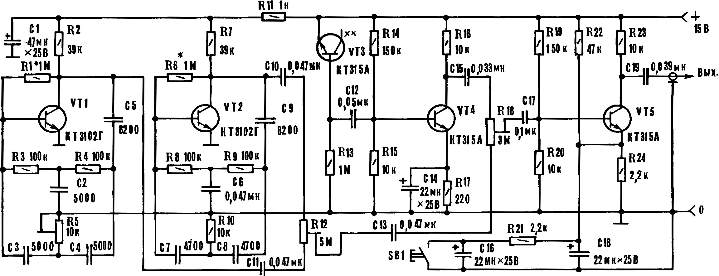
Fig. 3. Schematic diagram of the block "whistle" (click to enlarge)
Unit 3. Here (Fig. 4) again used RC oscillator with dual T-bridge, however resistor R14 is set to the threshold of self-excitation, so that the sound bell was the most natural. Timer DА1 generates pulses with a frequency of about 1 Hz, it is excessively large, the output voltage is reduced divisors RЗ, R4, then rectified by the diode VD1 and differentiated chain C3, R4, short sharp triggering pulses. Opening the button, include the bell, giving one a shot per second. If you reduce the resistance R2, the bells will become more frequent.
Fig. 4. Schematic diagram of the block "bell" (click to enlarge)
Unit 4. The outputs of all three sources of the sounds are mixed in the mixer (Fig. 5). Each input has its own regulator (R1-RЗ). The signals are summed at the gate field-effect transistor VT1. The total signal is fed to an external amplifier and CC the loudspeaker through a matching emitter follower VТ2.
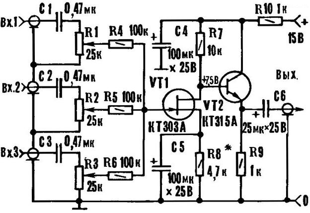
Fig. 5. Schematic diagram of the mixer
In this design you can use native timer or CREW foreign R555D. The transistors in RC-generators - KT3102 index G, T or CTV. Transistors for noise generators should to pick up on the maximum voltage of the noise from the KT315 with any index. Field-effect transistor in the mixer - type CT with any index. The rest the transistors can be such as, for example, CT, CT, KT315 and Diode etc. VD1 (Fig. 4) - any low-power silicon. All fixed resistors MLT with a capacity of 0.125 or 0.25 watts. Variable resistors may be of any type with feature A (Fig. 2.4) and In (Fig. 5). Oxide capacitors - type K50-6 25 V. Constant capacitors in the RC circuits-generators metalloboranes with tolerance 5%, others - any. The trigger button, for example, P2K, etc.
Most conveniently, each block can execute on a separate Board. Installation may be as hinged and print. Location details of non-critical blocks. Each block after Assembly, check and repair using high impedance head phone (earphone).
Supply voltage +15 V (tolerance + 12V). Noise generators set at the collectors of transistors with a voltage of +7.5 V by selection of the resistance base resistors (marked with asterisks). Paired resistors and capacitors in the bridge must be picked up possibly be exact, otherwise the generation will not occur. Voltage +7.5 V at the drain VT1 (Fig. 5) set selection of the resistance R8. For connection of all units with a mixer use a short shielded ends cable. The same cable is needed to connect the mixer with an external amplifier AF.
The power supply may be any low-to 15 V. All blocks preferably to install the chassis with the help of connectors. The main controls on display the front panel of the housing. The size and shape of the body is arbitrary.
Connect the output of the mixer with the AF amplifier and loudspeaker, apply power. Now in block 3 ("bell") adjust the resistor R14 for optimal sound when the button is pressed SВ1, there should be clicks and other extraneous sounds.
In block 1 it is desirable that the three main governance body were located on the front panel next. This is the handle of the resistor RЗ ("frequency"), the S1 button (enable "poof") and S2 ("steam"). Then they can be managed by the fingers of one hands. The unit 2 is only one operational button SВ1. The bodies adjust R5, R12 and R18 are on Board, they set up during commissioning and do not display on the front panel.
If your model train is equipped with an electronic speed control movement, then it makes sense to connect the regulator R3 block 1 with speed control of the train for a more coherent management.
In addition to audio additions to the model train, you can add and lighting design depending on your taste and capability of the Modeler.
Author: Y. Pakhomov