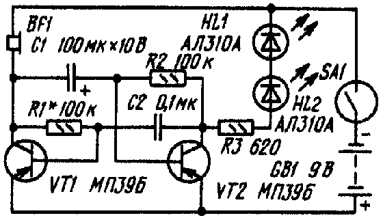
Simulator (Fig. 1) is an asymmetric flip-flop circuit made of two transistors. In one shoulder multivibrator included headset BF1, in the other series-connected LEDs HL1 and HL2. Both loads are serially - distributed the sound from the phone, then flashing LEDs - eye duck.
Turns on the multivibrator reed switch SA1 is approaching a permanent magnet while tilting toy duck or is brought in the form of a "magic wand" (it may be, for example, pencil, the end of which is masked a small magnet).

Fig. 1
Transistors can be any one of a series MP39-MP42, but with the current transfer ratio of not less than 30. Resistors - MLT-0,125, capacitor C1 - C50-6, C2 - MBM. The head - phone TM-2 or other small, impedance 100... 200 Ohms. Is listed on the scheme will approach the other LEDs. The brightness of the glow set the selection of resistor R3. Power source - battery "Krona", reed - CAM-1.
The establishment of the simulator is reduced to the selection of resistor R1 to obtain the characteristic sound of a quack.
Author: E. Brignevich, Kislovodsk; Publication: www.cxem.net


