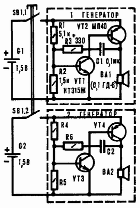
Electronic simulator, schematic diagram of which is presented on Fig. 1, mimics the sound of a siren. The device consists of two identical audio oscillator collected on transistors VT1, VT2 and VT3, VT4 different patterns according to the scheme asymmetrical multivibrator.
As a result of interaction close in frequency acoustic the vibrations emitted by the dynamic heads BA1 and BA2 working "Duo", the nature of the sound dramatically different from the usual tone the signal emitted by one head. The sound becomes a nice unusual color, becomes saturated, colorful, enriched by overtones. When placing heads at some distance from each other is observed the effect is close to the stereo.
The positive feedback made up of resistor R3 (R6) and capacitor C1 (C2). From the parameters of these elements depends on the basic operating frequency of generation, and also the volume reproducible dynamic head of BA1 (BA2) is the load generator. The divider of the resistors R1 (R4) and R2 (R5) creates the necessary the bias voltage on the base of VT1 (VT3) indicating the mode of operation for DC and AC current of each pair of interconnected transistors.
To exclude the influence on each other generators due to the galvanic connection, each equipped with an independent source power G1 and G2. Include simulator dual button SB1.

Fig. 1
In your device, you can use any transistors series CT, CT, CT, CT, KT315, CT, KT (n-p-n) and MP-MP, MP, MP, MP, MP39 - MP42 (p-n-p) by a factor current transfer base 30. Resistors MLT-0,125 or MLT-0,5, capacitors MBM, km and others. Dynamic head capacity 0,1-2 W, the resistance of the voice coil DC 4 - 16 Ohms. Instead, you can apply the electromagnetic telephone with primers coil impedance DC 30 - 200 Ohm (for example, DAMS-1, DEM-4m, TM-2A). In this case, the resistance of resistors R1, R4 should to increase. Push-button type switch KM2-1. Nutrition - elements 332, 343 or 373.
The establishment is to alternate the setting of generators. The first power source is connected to the first and selection resistor R2 achieve the greatest volume of sound signal. Then the same operation is repeated for the second generator. Immediately thereafter include both generator and listen to them together the effect of experimentally determining the best mutual arrangement heads (real structure). The operating frequency of the generators pick up, by changing the capacitance of capacitors C1, C2 within 0,033 - 0,25 µf. If their values differ, the nature of the sound will be different, but in their own way interesting.
Author: E. Sawicki, Korosten, Zhitomir region; Publication: www.cxem.net


