


")

The fraction of bursts of gunfire, screeching mines, heavy bass bombs Simulates… like the sound of the fight is pretty simple device, made just for three transistors.
As can be seen from the circuit diagram, simulator sounds of battle consists of self-excited generator of pulses of the multivibrator transistors VT1 and VT2, amplifier (semiconductor triode VT3) and dynamic head of BA1. And choose sound effects by users by pressing different buttons management.
To simplify the design uses a single common generator, the mode of operation change the relevant switches. In the "machine gun" this the multivibrator receives power directly from the battery GB1 via the switches S4 (includes simulator) and S1, which (thanks to the contacts S1.2, S1.3) in parallel with the capacitors C5, C7 connects a relatively large electric capacity C3 and C6, which ensures the "queue" with some frequency "shots". Optionally, adjusting the value of capacitors C3 and C6, change the frequency with which "scribbling gun". The amount of current of the transistor VТ3, shown in the diagram, set selection resistor R5.
In the simulation of the passage of the mines, the power is supplied from the pre-charged capacitor C1, when the movable contact of the group S2.1 switch thrown right in the diagram position. At the same time in the shoulder multivibrator group S2.2 includes the capacitor C4. As the discharge capacitor C1 voltage at multivibrator decreases smoothly, with increases the generated frequency and there is a sound like the screech of flying mines.
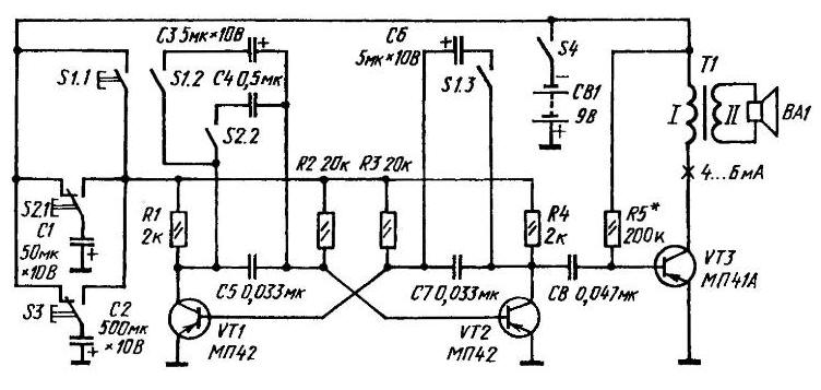
A circuit diagram of the device for imitation of sounds
Organization of supply of the multivibrator in the "rocket" similar - from the capacitor C2 via the switch S3. In this case, in the shoulders of the multivibrator only the capacitors C5 and C7. The sound that starts with a low note, gradually increases to a very high and as it fades away.
Signals simulated are amplified by a cascade on the VT3 transistor connected in the circuit with common emitter. His load is the dynamic head of BA1 in reservoir circuit of the transformer T1.
The supply simulator - battery "Corundum" or two elements 3336, are connected in series. You can use AC (adapter). In the quality of the switches S1-S3 is better to use the buttons or toggle switches with switch to its original position. As S1 and fit the switch ranges flat-blade from a handheld radio. Auto reset in the open position there is provided, if the selector knob to provide a spiral spring.
Circuit simulator is run from foil fiberglass. To her "print" sites are soldered with the corresponding oxide capacitors K50-6 or MBM (C4), KLS (S1-Sz, (C5-C8), resistors (all types MINTS, power up to 0.5 W) and other elements of an electrical circuit.
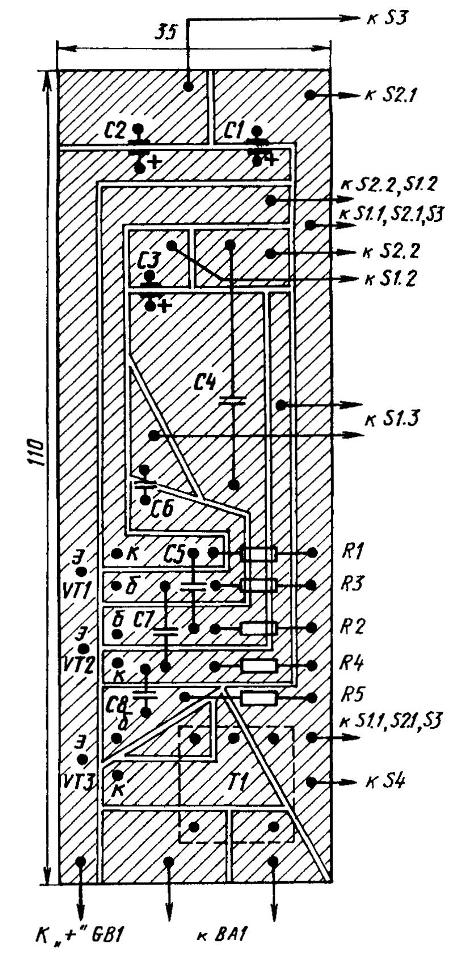
Circuit Board device for imitation of sounds
It is possible to replace used parts in their counterparts. In particular, instead indicated on the circuit diagram of transistors for others to come out series MP39-MPA as well (all of them) MP-MPA structure n-p-n. But in the last case would have to reverse the polarity power source and oxide capacitors.
The transformer T1 is output from the radio type Selga 404". Dynamic head - to 0.1 GM-8 or another with the impedance of the voice coil 8-10 Ohms.
Controls can be placed in the housing of the simulator or remote control, connected to the wiring Board of the flexible stranded wire in vinyl isolation. Dynamic head is mounted on the front panel, where this, drill holes with a diameter of 2-3 mm (under hardware and sound", located in front of the diffuser).
Correctly assembled device starts working immediately after it is turned on power supply.
Author: Yu Prokopcov