This simple device, assembled by only two transistors, is an electronic stopwatch, as it can be used to count intervals time set on the scale.
As capacitor C1 charges, the voltage across it increases, and the charging current gradually reduced. The drain current (and almost equal to a current source) decreases and decreases the voltage drop across the resistor R4. This leads to increasing negative the voltage on the base of the transistor VT2. When this voltage a certain threshold transistor VT2 is opened and starts the generator sound frequency, which it is assembled. Generation is provided by the presence positive feedback, which is fed from the winding 2-3 of the transformer T1 through the capacitor C2 to the base. Loudspeaker BA1 begins to play the audio signal, whose frequency is determined by the coil inductance and capacitance of the capacitor C2. Now with the toggle switch can be turned off
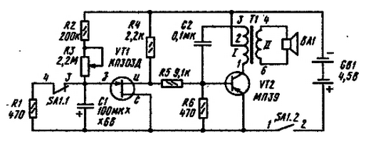
Schematic diagram of the stopwatch shown in the figure.

In the initial state shown in the diagram, the power to the unit from battery GB1 not served, and the capacitor C1 is discharged. To start the stopwatch include a toggle switch SA1. The contacts SA1.2 is supplied the power to the circuit, and the contacts SA1.1 opens and the resistor R1 is disconnected from the capacitor C1, which starts to charge. As long as the capacitor is discharged, the voltage on the gate field transistor VT1 relative to its source is equal to supply voltage +4,5 In and the transistor is fully open. Almost all the supply voltage falls, and the potential of the base of the VT2 transistor relative to the emitter is close to zero. In the result, he finds himself locked.
As capacitor C1 charges, the voltage across it increases, and the charging current gradually reduced. The drain current (and almost equal to a current source) decreases and decreases the voltage drop across the resistor R4. This leads to increasing negative the voltage on the base of the transistor VT2. When this voltage a certain threshold transistor VT2 is opened and starts the generator sound frequency, which it is assembled. Generation is provided by the presence positive feedback, which is fed from the winding 2-3 of the transformer T1 through the capacitor C2 to the base. Loudspeaker BA1 begins to play the audio signal, whose frequency is determined by the coil inductance and capacitance of the capacitor C2. Now use the toggle switch to turn the power off with the simultaneous discharge of the capacitor C1 through the resistor R1, having prepared a scheme to the next inclusion.
The time elapsed since power-up the switch SA1 until sound (shutter speed) is determined by the charge rate of the capacitor C1, because of what he called ramasedi. The speed of charging depends on the time constant of the charge, equal to the product of capacitance resistance G1 connected in series resistors R2 and R3. The larger the time constant, the slower charging of the capacitor and the more shutter speed. To change serves as a variable resistor R3. Under these scheme, the parameters of the elements the minimum shutter speed corresponding to the minimum resistance of the resistor R3, is about one minute and a maximum of about 15 minutes. If required smaller shutter speed, decrease the capacitance of the capacitor C1. If it decreases in 10 times the shutter speed is reduced in about 4 times. To install one or another exposure variable resistor R1 is necessary to provide a scale and to program it with using a regular stopwatch.
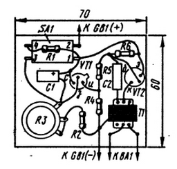
The circuit can be performed on the Board, shown in the figure, without printed conductors, using as reference points the findings of the details.

In the quality of the transformer T1 is used for any output transformer from small-sized transistor radio. Capacitor C1 must have minimal leakage. Therefore, it is advisable to use a tantalum type capacitor Or K52 with an operating voltage of 6 V.


