


")

As you know, the timer is a device designed to automatically connect electronic devices to the power supply or disconnect from him. To him traditionally have, for example, requirements such as small dimensions, power consumption and the voltage drop in the control circuit. Traditionally, the load included high current through the relay contacts. With the advent of powerful switching transistors in, say, IRLR2905, the need for a relay disappeared, which allowed to reduce considerably the dimensions of the timer. Such the transistor used in the timer circuit which is shown in Fig. 1. It capable of operating at a voltage of 7.5 V and can switch loads that consume current up to 30 A.
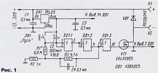
On the chip DA1 assembled a voltage regulator on the logic elements DD1.1, DD1.2 - voltage comparator, on DD1.3 - inverter, transistor VT1 - electronic key. Capacitors C1 and C3 provide stable operation voltage stabilizer, options chains C2R1 set the response time timer. The resistive divider R2R3 provides feedback in the comparator voltage and provides an abrupt switching of the comparator from one steady state to another.
Now about the device. After the filing of the supply voltage begins charging capacitor C2 through resistors R1 and R2. While the input of the logical element DD1.1, a high logic level, and the output is low. Field transistor VT1 is closed.
As the charging of the capacitor C1, the voltage at the input of the element DD1.1 is reduced. When it reaches the switching threshold of the comparator, the gate of the transistor there will be a voltage of about 5 V. the Transistor opens and the load connected to terminals X1, x2, will be available supply voltage. This is the mode on delay load.
To re-start the timer, press the SB1 button "Start". The capacitor C1 is discharged, the countdown will start again.
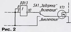
The timer worked off delay load, need the gate field transistor to disconnect from the exit of the element DD1.3 and connect it to the output element DD1.2. If the device to enter the switch SA1 (Fig. 2) the timer 'll be able to work in a mode on delay and delay mode off.
If you connect a load is inductive in nature, the nest should be shall be shorted by diode VD1, and to reduce the likelihood of a bounce when you turn on or off load to a capacitor C4.
Also indicated in the diagram, it is permissible to apply the chip CLA, and when change the layout of the circuit Board LE, CLA. The transistor can be any highlighted from the list given in the article "Powerful field the switching transistors of the firm INTERNATIONAL RECTIFIER," in "Radio", 2001, No. 5, p. 45. This, of course, the maximum dial-up timer current will be determined by the type of the applied transistor. Polar capacitor C2 should be tantalum surface mount low leakage current or K52 series, but then you have to increase the size of the Board. The remaining capacitors - K10-17. For low-load diode VD1 can be from any series CD, CD, CD, and for powerful - CDA-CDU, CDU, CDB or similar. Resistors - MLT. C2-33, P1-4, P1-12, button and switch - off any small.
Load current more than 1 A common power wire should be soldered as close as possible to the source of the transistor. If the current exceeds 8 A, the transistor should be set (by soldering) on the radiator. For the current 30 And its area should be 100… 150 cm2. When the supply voltage is 15 V or more, it is recommended to enable consistently with button resistor 10…20 Ohms to reduce the discharge current of the capacitor and protection of the contacts button from scorching.
To increase the voltage at which to operate the timer to work voltage of the transistor, it is necessary to use a stabilizer DA1 high-input voltage.
Own current consumption of the timer is determined mainly by the current stabilizer.
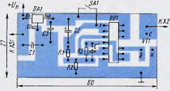
Most of the parts of the device is placed on the circuit Board (Fig. 3) from sided foil fiberglass.
The establishment timer is to install the required delay time selection resistor R1 and, if necessary, of the capacitor C2. For these in the scheme the values of these elements, the delay time was approximately 13 min.
During testing, the layout of the timer when the current is 5 amps the voltage drop across the transistor amounted to 0.1 V, and dissipated in it, power is 0.5 W, which indicates good efficiency of the device.
Author: I. Nechaev, Kursk