


")

The primary element of a conventional mechanical clock is the pendulum or balance, which are driven by a weight or spring. These watches require regular and frequent winding, which creates some inconvenience.
Many designers for a long time worked on the problem of creating a clock without the weights and springs, the result is a Electromechanical watch. In them the pendulum is actuated by the electromagnet, which is powered by a source of electric current. When the pendulum approaches the equilibrium position (Fig. 1), the contacts associated with it, are closed, and the electromagnet coil current flows. The pendulum strengthened the armature of soft iron, which is attracted to a stationary electromagnet.
Fig. 1. Electrical contact hours.
Electromechanical watch very sparingly consume battery and have good accuracy. But they have a weak point - contacts, closing the circuit of the electromagnet. After only one year they have to withdraw millions of times, so after some time electric clock start to run wide. And if the watch are very small, for example wristwatch, miniature contacts in them are even more unreliable. With the advent of transistors, it was possible to create a contactless electric clock.
Diagram of a contactless electric clock on the transistor shown in Fig. 2. The pendulum reinforced permanent magnet, at which motion in the coils of the stationary coil induced EMF. One of the windings of the coil is connected between the base and the emitter of the transistor, the second -- in the collector circuit.
Fig. 2. The electrical circuit of the clock on the transistor.
The center of the pendulum (magnet) intersects the axis of the coil is in equilibrium position. When the pendulum oscillation in the coil L1 is induced EMF, the form of which is illustrated by curve 1 (Fig. 3). In this figure, curves, carried out by a continuous line, are plots of voltages and currents induced by the motion of the pendulum from left to right, and the dotted line is from right to left. The winding ends of the coil L1 is enabled so that when the pendulum approaches the equilibrium position, at the base of the transistor appears negative relative to the emitter voltage. It arises when approaching the magnet to the coil, due to the increase of the magnetic flux that flows through its coils. In the equilibrium position of the magnetic flux through the coil reaches a maximum. At this point, the voltage becomes zero. Further, the magnetic flux begins to decrease and the EMF changes its sign to the opposite. When the magnet moves away from the coil, the voltage at its ends almost disappears. During the second half cycle pattern repeats: when approaching the magnet to the coil in the coil L1 is induced this EMF, which is the base voltage is negative. Under the action of this pulse voltage in the base circuit passes a current (curve 2) and the transistor is unlocked (Fig. 3).
Fig.3. Plots of voltage, current and anergy of the pendulum for hours scheme, shown in Fig. 2.
A - the amplitude of oscillation of the pendulum,
About the equilibrium position.
The direction of turns of the coil L2 in the circuit of the collector, such that when it passes a current collector (curve 3) the magnet is attracted to the coil. Its motion is accelerated.
The oscillation frequency of the pendulum as in normal hours is almost entirely determined by its physical parameters: length and mass distribution. The mass of the pendulum is determined mainly by the magnet and the details of its mounting. The pendulum connects a dial mechanism with the dial, and the watch is ready.
Design hours. For the manufacture of watches on the transistor is quite suitable any pendulum clock or clocks". They only need to alter the trigger device and, of course, to remove a spring or a weight; their function will perform a battery.
In normal hours release device, resulting in the movement of the pendulum is shown in Fig. 4,and. It should be remade, as shown in Fig. 4,b. Axle 1 napaimiut the rocker arm 2, which are freely dangling earring 3. The motion of the pendulum to the left earring slides along the beveled side of the tooth of the ratchet wheel 4 and under the action of its gravity, falls from the top into the gap between the teeth. The motion of the pendulum to the right earring rests on the cool side of the tooth and rotates the ratchet wheel to the left by one tooth. To fix the position of the wheel and not let him turn to the right, lies on top of him with one edge of a petal-dog 5. The second edge of the petal freely rotated around the axis 6. During rotation of the ratchet wheel to the left petal slides along the beveled edges of the teeth and, springing from their peaks, rests on the steep edge of the teeth.
Fig. 4. Device trigger ordinary hours (a).
The device of the clock mechanism on the transistor for converting the oscillatory motion of the pendulum into rotational motion of the arrow (b).
The assembled clock mechanism, made of ordinary "clocks" as shown in Fig. 5. Rocker, earring and petal-dog this watch is made of tin. The magnet can be used by anyone. Its volume should not be less than 3-4 cm 3, as it needs to hold the load 100-200 g. In the described construction utilizes an annular magnet from a loudspeaker with a diameter of 35 mm. For adjusting the clock magnet attachment should include moving it up and down. If the clock is fast, the pendulum (magnet) should be omitted.
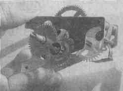
Fig.5. The assembled clock mechanism.
In the clock generator (Fig.2) can work any floatable transistors, for example, type A13-apparatus P15. The operation of the generator does not depend on the magnitude of the gain of the transistor current. Diode D1 can be applied type DB-DG. Instead of the diode you can use the emitter or the collector transition germanium alloy transistor, which gets the output of the collector or the emitter. If the generator (Fig.2) applied to the transistor of conductivity n-p-n, the polarity of the battery and the diode D1 should be reversed.
The solenoid coil can be wound on a plastic or paper frame with an inner diameter of 20, 48 and outer width of 8 mm. Wind the coil need two wires in bulk to fill. Wire diameter - 0,09-0,15 mm After winding it is necessary to check whether there are no short circuits between the obtained two windings. The start of one winding is connected to the other end and to connect the output of the emitter of the transistor.
Author: N. Goryunov, A. Pushkin; Publication: N. Bolshakov, rf.atnn.ru