


")

This device is intended for use him in the hallway of the apartment to automatically turn off lights after 30..,90 seconds after switching it on, the button SB1 (zvonkovic) or SB2 (inside the apartment). This time enough to undress.
Diagram, Fig. 1.3, consists of a thyristor VS1, which will be in the open state during the time until the charge of capacitor C1. Button SB2 can be installed next to the existing in the switch apartment light S1 (switch convenient to use if you need light for a long time, for example when you move about). Button SB1 is the outside of the door and is zvonkova. When pressed it will buzz and turn on the hallway lights on set when you set up the time interval that will allow the light to come to the door.
When the operation of the circuit of the machine in the mode of lighting the lamp EL1 will glow dimly, as it works on one half-wave of the mains voltage, but it's enough to light and increase the brightness by increasing power light bulbs.
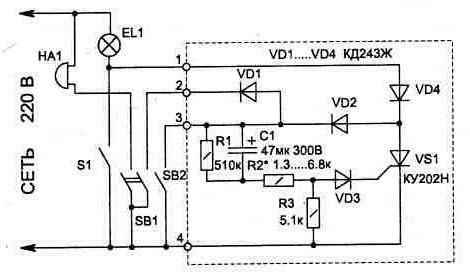
Fig. 1.3
If desired, the circuit easily to Supplement another button - SB3 (included in parallel with the button SB2), which be associated with the door and if opened, will turn on the light. The device can find and other applications, for example for switching on lights in the basement. In this case, the button SB1 and the call is not needed, and the lighting time can be increased by the capacitor C1 larger capacity (the circuit has a capacitor type C50-29-300) or picking up resistor R2. For stable operation of the circuit leakage current the capacitor should be minimal. As a button SB2 is convenient to use any two-piece light switch, tuning one section for use it as button. For this purpose, under the movable contact enclosed porous rubber, which will not allow one section of the switch to be in a fixed state after pressing it. Available the call button can be modified, adding its another contact, but if you have a relay with an operating voltage of 220 V you can do one set of contacts. In this case the relay is connected in parallel with a call and when it sounds your contacts (instead of the second a contact group button) discharges C1.
The topology of the printed fees and arrangement of the elements shown in Fig. 1.4.
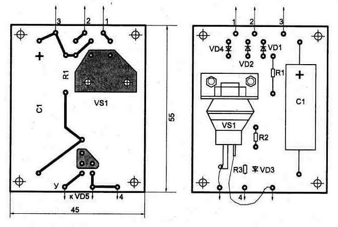
Fig. 1.4
Compared with other published devices of similar purpose, this scheme has a smaller size, does not contain scarce parts and easier to manufacture and connect.
Sometimes you want to have constant backlight, for example in the corridor. The backlight consumes a lot of energy (7…15 watts), but more economical, if it will only work in the dark. To turn on the backlight manually always convenient. Moreover, it can successfully perform automation.
The electrical circuit of the automatic switch shown in Fig. 1.5. It consists of an amplifier (VT1) of the signal from the photosensor R2, generator pulses on the unijunction transistor VT2 and triac switch VS1.
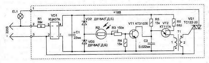
Fig. 1.5
Photoresistor depending on the light conditions change its resistance 1 kω (maximum light) to hundreds of ohms (in the dark). This signal is amplified by the transistor VT1, which, as a rule, is saturation or closed depending on ambient light sensor R2. If the transistor VT1 is closed, the generator works on the transistor VT2. The principle of operation of the generator based on the property unijunction transistor to discharge the capacitor C2 via base 1 when exceeding the voltage threshold value (base 2). Periodic the discharge of capacitor C2 through the winding 1 of the transformer, in the secondary forms the winding of the opening pulses of the triac VS1.
Load triac can be lamp power from 5 to 2000 watts the control circuit consumes no more than 1.3 watts and to reduce size is transformerless.
For normal operation of the circuit is necessary to photosensor located remotely from the lighting area.
The desired sensitivity of the circuit to the light is installed the resistor R3.
The device incorporates details: R2 type SF-19 (FSK-1), R3 - JS4-1, S1 - K52-1B 63, C2 - K10-17. Zener diodes VD2, VD3 valid replace DB, IN, the Transformer T1 is wound with a wire diameter pelsho 0.18 mm on a ferrite ring MNM size CHH mm and contains in the winding 1 - 80 turns, 2 - 60 turns. The sharp edges of the frame ring is rounded with a file before winding.
A printed circuit Board for the circuit and layout elements shown in Fig. 1.6 . A heat sink for the triac when necessary its load capacity of 1000 watts.
The housing may be any of the dielectric materials.
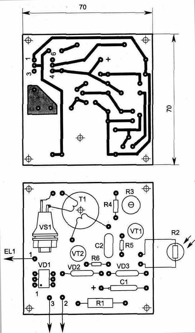
Fig. 1.6
Publication: www.cxem.net