In order to save the battery, but also because of the unreliability power switch I decided to make for his domestic multimeter "Electronics IMC-01" power off timer in one of the schemes described in [1].
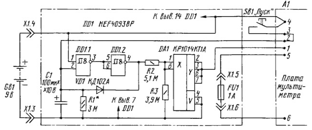
Each of them has both advantages and disadvantages. The first scheme (author I. Nechaev) provides a clear power, but a large voltage drop the key inverters do not allow you to utilize the resource of the battery battery. The second scheme (the author Petrov), by contrast, provides a minimum the voltage drop on the key, but has a long time smooth off (about 30). It was therefore decided to combine the advantages of these devices, getting rid of the weaknesses. Diagram of the timer and its connection to the multimeter shown in the figure.

The operation of the device is similar prototypes: while pressing the button SB1 charging the capacitor C1, which gradually discharged before switching logic inverter DD1 and, accordingly, turn off the electronic key DA1. Given that the inverters DD1 in the scheme in Fig. 1 in [1] are not the key for the current power, there is no need to connect them in parallel and you can only use one of them. The inputs of the free items must be connected to one pin of the power source.
The device is assembled on the PCB of bilateral foil fiberglass size 24x26 mm method volume-surface mounting. On one side of the Board contains all the elements of the timer and the fuse FU1 from the composition the multimeter. On the other contact pad battery "Krona". At the corners of the Board soldered strut towers with a height of 11 mm, which are both conductors, connecting both sides of the Board. The device is connected to the motherboard multimeter the harness is made of flexible wire in Teflon insulation, and is installed in the battery compartment instead of the regular ones of the contact pads.
In the device used chip HEF4093BP Philips, analog CTL. In as C1 capacitor used from the K53-19 100 UF voltage of 6.3 V. tests have shown that it reliably operates from a fully charged storage the battery voltage of about 10 V. the real capacity of the capacitor 130 µf delay time is about 3 min during consumption of multimedia services current about 7 mA. The voltage drop across the key does not exceed 40 mV.
All resistors - MLT-0,125. As the button SB1 used microswitch MP-7 installed instead of PD9-1. The number of contact pads on the PCB multimeter A1 (see Fig.), and contacts X1.3 - X1.6 correspond to the markings on the original scheme multimeter [2].
Literature
Author: S. Nebraskan, Saransk, Mordovia


