


")

Everyone knows that time spent by children for a different game consoles, often exceeds all the reasonable limits. And often no arguments adults do not help to convince the guys to take a break and do something else useful . It is here that will help you to simple "electronic assistant" - timer.
The device is designed to disconnect the game console via a certain time. About a minute before the set break, emit a warning signal. During this time, you should stop the game and disable the console regular switch. In the forced shutdown power. After disconnecting the device must be in the off position 1.5…2 hours to completely discharge the timing capacitor. When you try to enable the console ahead of time will sound a warning signal, the power is not served.
Diagram of the device shown in Fig. 1.
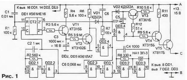
On the elements DD2.1 and DD2.2 assembled the generator of rectangular pulses with a repetition period of about 1 s. From the output generator pulses to the input of the counter DD1. After coming 8192 th pulse (approximately 2 h) at the output 213 of the chip DD1 appears log. 1 and through the opened transistor VT1 starts charging the capacitor C3. Transistor VT2 open. The inputs 5 and 6 of the element DD2.4 set log. 0, it the outlet 4, respectively, of the log. 1, which is supplied to the 8 inputs of the element DD2.3 and 6 item DD3.4. A high level at the input 8 of the element DD2.3 permit the submission of trigger pulses to the input of the sound signal, which is made on the elements DD3.2 and DD3.3.
A single signal input 6 element DD3.4 translates this element in the mode expectations, and the appearance of high level at its input 5 output DD1 26 (approximately 1 min) low level output closes the transistors VT4 and VT5. thereby stopping the power of the consoles.
When power is applied, a short pulse from the output of the differentiating circuit C6R7 is fed to the input 5 of the element DD3.4. If the capacitor C3 is not discharged (from the end of the previous game was less than 1.5…2 hours). at the entrance 6 DD3.4 - log. 1. the output DD3.4 there is a log. 0. VT3 transistor is turned on and captures this state. As a result a beep sounds, the power the gaming part is not served.
A drawing of the circuit Board of the timer shown in Fig. 2.
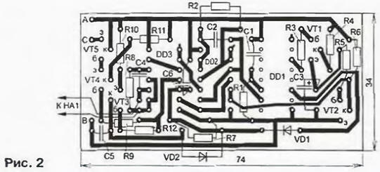
Correctly assembled device begins to work immediately and in the establishment does not need. The consoles determine the capacitance of the capacitor C2 and the resistor R2.
A break in the work is determined by the elements C3, R5 and transistor parameters VT2. Printed circuit Board designed with installation in "Subor" SB225-B. therefore, when using the timer in the console "Dendy" or "Sega", you may have to change its size.
The timer is connected in the gap plus the power lead of the console: a point - to the power supply unit, With - to your game console. Point To connect with sub-zero the power lead.
To reduce losses of power supply voltage is recommended that you replace the transistor VT5 on the transistor structure p-n-p (for example, CT or CT with any letter index). The emitter should be connected to the conductor A. the collector - to With base - to upper circuit on the output R11, disconnecting it from the circuit And the Emitter of the transistor VT4 need to connect to a common wire, and the value of the resistor R9 to increase to 43 ohms. The transistor VT4 need to pick up with the current transfer ratio base not less than 100.
Author: Mikhail Fedotov, G. North of the Tomsk region.