


")

Some manufacturers of household appliances, battery-powered (for example, electric shavers), is recommended in order to avoid their damage control hours charging time. This work is expedient to entrust the timer. Offer in this article, the design can be used in other cases where need a timer with an upper limit of the count in a few hours.
Schematic diagram of the timer that was designed for electric shavers "Kaiser V5-541FC" firm "Mikma". shown in Fig. 1. Eats it from the source a voltage of about 10 V, which includes the VD3 diode bridge, the Zener diode VD2, the capacitors C4 and C3, resistors R7 and R8. On DD1 chip is assembled with a single-shot the required pulse duration, and to connect the load to the network used thyristor optocoupler U1.
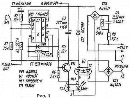
When you connect the timer to the network at the output of differentiating network C1R2R3 is formed by a short pulse, which is input to the S most significant bits counters circuits DD1 and installs them in one state. At the output 15 chip DD1 present high logic level, transistor VT1 outdoor bypasses the led of the optocoupler, and the load is de-energized. The current bridge flows through VD3 Zener diode VD2, transistor VT1 and the radiating element with a red led HL1 glow. The latter lights up and indicates the absence of charging. Signal a logic high through the diode VD1 is input to Z DD1 and chips prohibits the operation of the generator.
When you press the SB1 triggers counters DD1 chip installed in the zero state, the transistor VT1 is closed. Current rectifier bridge VD3 begins to flow through the led triac optocouplers U1 and radiating element LEDs HL1 with a green glow. OPTRON opens and connects load (charger shavers) to the network. Current. passing through the emitting the led of the optocoupler. has a pulsating character and reaches its maximum the value of 20 mA in the moments of transition of the mains voltage through zero.
At the same time starts the generator, collected at three inverters chip DD1 and elements R4 and C2. The oscillation frequency is about 1.5 Hz.
The period of the pulses at the output 15 of the chip DD1 equal 32768/1.5=21845 = 6 h and later half of the period that corresponds to the three hours required for charging battery, this output is a signal of high logical level. The VT1 transistor opens, bypasses the led of the optocoupler and the current through it and the load stops. Now the current bridge VD3 again will flow through the radiating element HL1 led with red light, which will light up, signaling charging is finished. Simultaneously a signal of high logical level through the diode VD1 will be transferred to the Z input circuits DD1 and will stop operation of the generator.
During breaks in the supply line voltage, not exceeding one hour, the capacitor C3 does not have time to discharge fully, and when the voltage the battery charging process will continue. If a break in the supply voltage exceeds the specified time, when re-activated, the counters of the chip DD1 established in one state and the charging will not resume that will prevent its damage due to possible overcharging. If a low probability of breaks power network button SB 1 and the resistor R1 can be excluded by connecting R DD1 chip to differentiating the chain С1R2R3. and the input S to the output 7. In this case, the countdown will start immediately after turning on the timer in the network, and for large breaks in the supply voltage it will start from scratch.
All elements of the timer, except for the plug, button SB1 and output jacks X1 and x2. mounted on the PCB size 42.5x60 mm (Fig. 2).
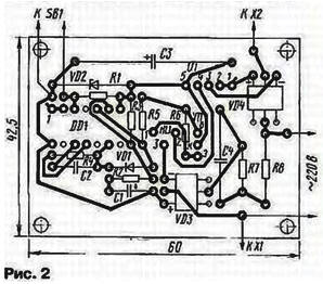
The fee is calculated to install resistors MLT. capacitors K53-16 (C1). K73-17 (C2, C4), K52-1 (C3). Capacitors C1, C2, C4 are arranged parallel to the circuit Board. Diode VD1 - any low-power silicon, Zener diode VD2 is the voltage stabilization 9… 10 V. Rectifier bridges - for a voltage of less than 50 In (VD3) and 400 V (VD4). Transistor VT1 - any low-power silicon structure n-p-n.
In place of C4 can work in any metal film capacitor, for example. K73-16 or K73-17, with a rated voltage not less than 250 V, and paper or metallorum-tion for a rated voltage not less than 400 V. the Oxide capacitors -any type.
Button SB1 - micro switch MP-1 with the plunger of the cap is faulty of the transistor.
Two-color led HL1 can be replaced ALSO, KIPDA-M, IPDB-M, KIPDA-M, IPDB-M, KIPDA-M, KIPDA or two conventional LEDs. It is important that the color of the glow to indicate these conditions the timer match given because it uses the fact that the voltage drop across the green led light more than red.
Thyristor optocoupler AOG permissible to replace AOD, AOB, or AOV to set the triac optocouplers series AO with any letter index, VD4 rectifier bridge becomes unnecessary.
Circuit Board, button SB1 and socket X1, x2 mounted on plastic box size 80x64x38 mm from industrial charger ZU-01M. On one of the walls of this box already had the pins of the plug.
When creating a timer in place of C2, a capacitor 330 pF. close the jumper conclusions capacitors C4 and parallel to the findings capacitor C3 to solder a resistor of 10 ohms (which is required for fast - one minute - discharge C3 in the configuration process). The timer should be be connected to DC or AC voltage 36…40 In this the moment to moment needs to erupt emitting element of the led HL1 with green glow and light up with red. When you press the SB1 instead of red turn the item with a green glow, and after about 16 again with red, then, the operation mode of the led HL1 should not change.
Further, the selection of the resistance of resistor R4 should set the time load. You need to put in place the capacitor C2 shown in the equation face value and to output 12 of the chip DD1 and to the negative terminal of the capacitor C3 connect the DC voltmeter. By clicking on the button SB1, count the number the pulses on pin 12 of the chip DD1 for 1 min, - they should be 90 or 91. If more pulses, must in proportion to this excess to increase the resistance of the resistor R4, and if less - reduce.
After that, by removing the jumper from the terminals of the capacitor C4, check the operation of the timer from the network in the battery charging mode of the electric shaver. Wherein the first it will be helpful to reduce the capacitance of the capacitor C2 330 pF, and then to increase to 0.33 µf and remove from the terminals of the capacitor C3 additional resistor.
The timer can work with other loads. Time to enable it easily change, counting the capacitance of the capacitor C2 or the resistance of the resistor R4. For control more powerful consumers can use electromagnetic relays 220 V. connected to the output jacks of the timer and thyristor (Fig. 3) or triac (Fig. 4) the key.
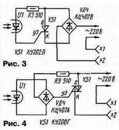
Diode VD4 bridge (Fig. 3) needs to be calculated at the required load current.
Author: S. Biryukov, Moscow