


")

Tea lovers know that depending on the manufacturing technology it can be divided into two main types - green and black. For good brewing black tea should soak it in boiling water to 4 minutes to 7 and green minutes. If the brewing time is greater than a specified interval, the welding of tea leaves were starting to use harmful substances (which confirmed by medical research). The timer will help to exclude this possibility (it is possible to apply the led of any type).
In the scheme uses: the capacitors C1 - type K73-17V 400 V; C2…C4 - type K50-29 or K53-4A 16 In; C5, C6 - any small. The resistors are suitable for any type with power dissipation, not less than indicated on the diagram. Transistor VT1 you can replace CTA, B, CT, the Zener diode will fit any voltage stabilization 9…13 V. as switch S1 you can use the button from disassembled toggle switch type MT-1 and S2 - compact switch. Mains fuse F1 can be made of a copper conductor with a diameter of 0.04 0,08… mm.
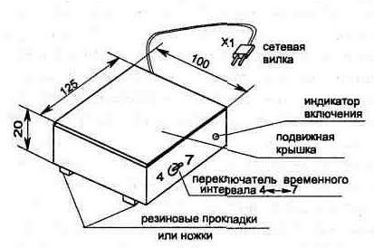
Fig. 1.29. The appearance of the timer
The timer will need to turn on and off, so how it is done in the form of a stand for the teapot and turned on when you install it kettle or cups of tea. The timer (Fig. 1.29) has two time intervals 4 and 7 minutes, one of which is set by switch S2.
intermittent beep alert system creates any type (SN-1, SN-22, SN-18, SN-3).
The response time of the timer depends on the capacitance C4 and resistors R4…R7 (setting more convenient to carry out the selection of resistors). Frequency sound depends on the values of R9 and C6, and the intermittent nature of the sound is set R8 and C5.
Powered transformerless device according to the scheme directly from the mains through a switch S1 (see Fig. 1.30) which is triggered under the weight. At power-on timer led lights HL1
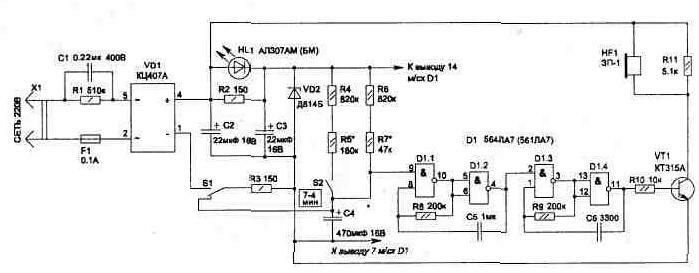
Fig. 1.30
A printed circuit Board, and the elements in it shown in Fig. 1.31 and 1.32. The elements are attached by soldering to the pads. When using the chip D1 type 561 LA7 pads in place install when you run the PCB should be divided according to location conclusions.
The timer setting start with an interval of 7 minutes at the open switch S2, selecting the value of the resistor R7, the Interval is 4 minutes configured when the closed switch S2 resistor R5.
The overall dimensions of the device do not exceed the dimensions HH mm. Upper cover is made of heat-resistant dielectric material (thick fiberglass or plastic). It is attached to the loop so when you install it light weight fire button S1.
This timer is in the kitchen can be useful for other goals, when for cooking requires the exact observance of the same time intervals.
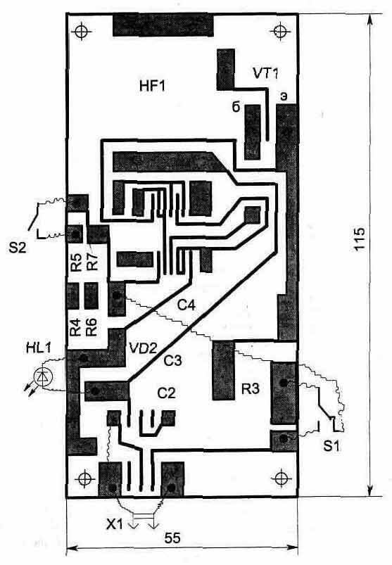
Fig. 1.31. A printed circuit Board,
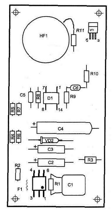
Fig. 1.32. The location of the elements from the printed conductors
Publication: www.cxem.net