It is likely that many, sitting in the morning in the bus or taxi, start remember: "And switched off the iron?". After some time develops into doubt panic. Stop the transport and ran back home. After some fuss with the front door, the Elevator and the door to the apartment, catching his breath, we find that iron still was off. However the mood for the whole day is ruined, and at work provided with a reprimand for being late. But this is not so bad. In another scenario (and not iron off and saving thought not visited) that could have ended much worse.
Several times when dealing with these situations and not wanting to bring the matter before the troubles, I decided to make a device that limits the duration of the connection iron or another appliance to the network. The idea is that by including iron in network using such a timer and pressing the button "start" to get the opportunity to stroke clothes, for example, 15 min, after which the iron will be automatically off. Not a problem if not handled press the button again to continue iron.
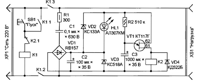
Diagram of the timer shown in the figure. Since it is a safety device, special the focus during development was paid to ensuring reliability. The number of parts minimized, as switching elements used electromagnetic relays.

Operates the unit as follows. After clicking the button SB1 start relay K1 works and it locks automatically closed contacts K1.1. The Contacts K1.2 and K1.3 connect to the network load, poluchennuyu to the socket XS1, and the actual timer. Rectified by a diode bridge VD1 voltage stable on the level approximately 20 connected in series In the led and Zener diode HL1 VD3. Excess extinguishes the capacitor C1 and the resistor R1 limits the amplitude of the pulse the charging current of the capacitors C1 and C2 at the moment of inclusion. The voltage applied the Zener diode VD2, during normal operation is less than its voltage stabilization, but in case of a break in the chain of HL1 led the Zener diode prevents dangerous the increase of the rectified voltage. Cliff is quite possible, if the led mounted out Board of the timer and connected to it by wires. With guaranteed the strength of the connections of the Zener diode VD2 can be omitted.
Since the relay K1 and the appearance of voltage In 20 starts charging capacitor C3 through the resistor R2. The voltage on the capacitor is slowly growing, and as soon as its value exceeds the threshold for unijunction transistor VT1, it will open, the relay K2 will work, contacts K2.1 will break the circuit of the winding of relay K1, that will lead to the last break contacts and disconnecting the load from the network After a few seconds the capacitor C3 is completely discharged through the plot the emitter-base of the transistor and the relay coil K2. The timer is returned to its original state and ready for a new integration button SB1.
When specified on the diagram the values of resistor R2 and capacitor C3 duration exposure - about 15 min. If there is a need to change it, instead constant of the resistor R2 can be set serially connected variable (470 ohms) and permanent (39 ohms). The adjustable range of approximately 0,5...15 min.
The maximum power load that can be connected to the timer depends from the properties of the relay contacts K1. The author was applied relay RP wound for 220 VAC and three groups of contacts, powerful enough for switching electric iron power exceeding 1 kW.
As used K2 relay JZK-20F with one group of contacts on switch. It can be replaced by another with similar contacts and a voltage not exceeding 12V at the coil resistance not less than 400 Ohms.
Author: Vladimir Volodin, Odessa, Ukraine


