During the hot summer season sale fans in stores significantly increase. Simple fans that flooded the market, have normal functions control (on-off) and several rotation speeds. Adding to this the fan is a simple electric circuit, you can control it with the inclusion of by means of a sensor and not to worry about turning off, as provided for in the scheme the timer automatically switches the fan off after a set time.
The scheme contains a minimum of parts. The use of MOS circuits allows you to power the circuit even nesterilizovanny voltage in the range 8...15 V and not worry about electrical disturbances. The feature of the device is to use counter CIA - 14-bit asynchronous counter with sequential shift. It allows you to program the delay time turn-off load in the range from 2 to 160 min. (for these in the scheme of values of RC-elements). As stated in the description, the counter is reset to zero by feeding the input of the positive pulse R duration of not less than 550 NS. The contents of the counter is increased by negative slope (slice) pulse input Outputs S. the counter is made from 1, 4...14 bits.

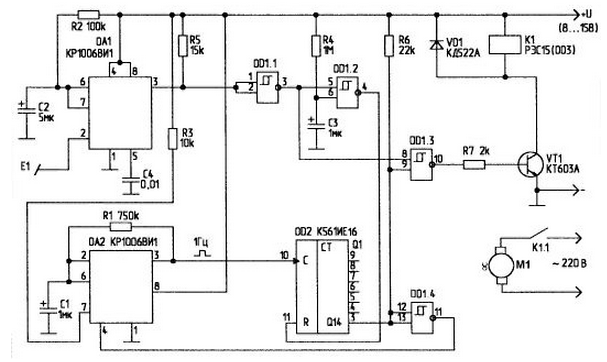
After powering on the circuit, thanks to the chain R4-C3, through which the input element DD1.2 is low on charge time of the capacitor C3, and the output DD1.2. accordingly, high, DD2 counter is set to zero. When a low logic level at the input R DD2 counter counts the pulses at 1 Hz, generated by multivibrator DA2 (timer CREW mode self-oscillations).
On the chip DA1 sensitive sensor is implemented. In the initial state at the DA1 output is a logic low (logic 0). When you touch touch plate E1, which can be done, for example, in the form of small tokoprovodyaschaya platform (label) on a stand-alone fan casing, the DA1 output a signal of logical "1". The peculiarity of such inclusion in DA1 the fact that the sensitive activation input (pin 2) of the chip reacts CREW even on the human touch gloves (through clothing, etc.). The length of the wire from the sensor E1 to the entrance DA1 should be minimal. Stable operation of the touch node was observed when the length of conductor is not more than 15 cm the Length of the output pulse DA1 is determined by the values of R2 and C2 and is in this version 2 C. This time is sufficient to double-invert elements DD1.1 and DD1.3 to open the transistor VT1 and enable relay K1, contact K1.1 which commute a fan of the M1. At the same time a positive pulse (after inverting element DD1.2) resets the counter DD2.
Programming required hold-off node is a connection jumper the corresponding output of the counter DD2 to the input of logic element DD1.4.
When specified in the scheme to bridge the time delay maximum 160 min. After DD2 counter counts the number of pulses corresponding to given the delay, the output DD2 is set to "1" which is inverted element DD1.4 and stops the multivibrator DA1. At the same time this "1", since the other input of the element DD1.3 - also "1" output from DD1.1, shape the output DD1.3 "0". which leads to the closing of the transistor and the relay and load. The circuit remains in this condition until the next exposure on the sensor E1.
Author: A. Kashkarov, G. S. Petersburg


