


")

The primary system clock plus the secondary network is long and well proven in shops factories, railway stations and offices. If instead bulky relays and mechanical driving mechanisms to apply and chips transistors, the system can receive new life.
The author, using modern element base, has tried to create the most simple, compact design of primary hours for 5 - 7 secondary. The device has dual power, i.e. it works on 220V and automatically switches to backup power battery "Krona" in the case network disconnection. The watch will work in offline mode, up to five days. The average current consumption from the battery is 1.5 mA. Accuracy - ±4 in month.
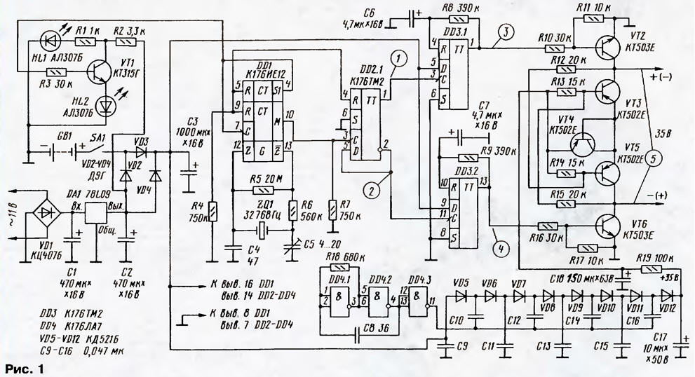
Diagram of the device shown in Fig. 1. To power the device from AC current 220 V required mains transformer (not shown), providing the secondary winding voltage of 11 V. the Power in this case does not play a role, the smaller the better, because the current consumption is very small. AC voltage rectified by a diode bridge VD1 and stabilized chip DA1.
(click to enlarge)
Generator minute impulses assembled on a chip DD1 according to the standard scheme, described, for example, in the S. Biryukova "Primary quartz watch" ("Radio", 2000, No. 6, pp. 34, 35). These pulses arrive at the input of flip-flop DD2.1. With outputs trigger antiphase sequences come in two shaper short pulses, which are collected on the triggers DD3.1 and DD3.2 (see chart on Fig. 2). The pulse duration is about 2 s, and the period is 60 seconds.
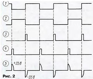
Transistors VT2 - VT6 assembled switch the polarity of the voltage. When receipt of a pulse from the trigger output DD3.1 will be open transistors VT2 and VT5 (VT3 and VT6 are closed). When receiving a pulse output from the DD3.2 transistors VT6 and VT3 open, a VT2 and VT5 will be closed. The polarity of the pulse at the output of the device would be reversed (figure 5 - figure 2). The transistor VT4 performs the role of the diode.
The polarity switch is powered by a Micropower voltage Converter, generator which assembles the elements of DD4.1 - DD4.3, and the multiplier - VD5 - VD12 and C9 - C16. Defined in the diagram of capacitance storage capacitor C18 (if you charge it up to 35 In) is sufficient to trigger the seven secondary hours. Resistor R19 does not allow to overload the Converter at the time of movement of the arrows.
Transistor VT1 assembled a progress bar for hours. Pulses with a frequency of 1 Hz arrive at the base VT1 from the output S1 of the counter DD1. LEDs light up alternately HL1 and HL2. In the absence of AC power to conserve battery energy of the node the display automatically turns off.
There is one feature that allows you to translate back the clock. For this need to quickly change the polarity of hours to the output of the device to to watch in succession came the pulses of one polarity. Each such switch (after activation) reduces the reading of the clock for one minute. This is due to feature of stepper motor.
If the number of connected hours is low, the transistors VT2 and VT6 can be CTI, a VT3 - VT5 - KT361 I. Diodes VD2 - VD4 - germanium series D9 with any letter index.
For an accurate start-up hours, you need to install additional elements in the node on the chip DD1, as is done in mentioned by the article author
Author: V. alferiev, Poltava, Ukraine