


")

In many enterprises, institutions, schools, other public places installed dial electric clock. They eat from the so-called primary hours, which often fail. In such cases, the author offers to replace them with simple home-made devices.
Primary quartz watches have high precision, ensure accurate start, as well as rapid traverse forward, what is needed after interruptions power, and when daylight saving time and return to winter. They characterized by small size I. importantly, capable of operating at 40 secondary hours.
A schematic diagram of such a clock is shown in Fig. 1. It is developed on the basis early publications of the author of the article in the magazine "Radio". No. 10, 1985 In new watch instead of relays used electronic keys, which allowed to increase their reliability and increase service life.
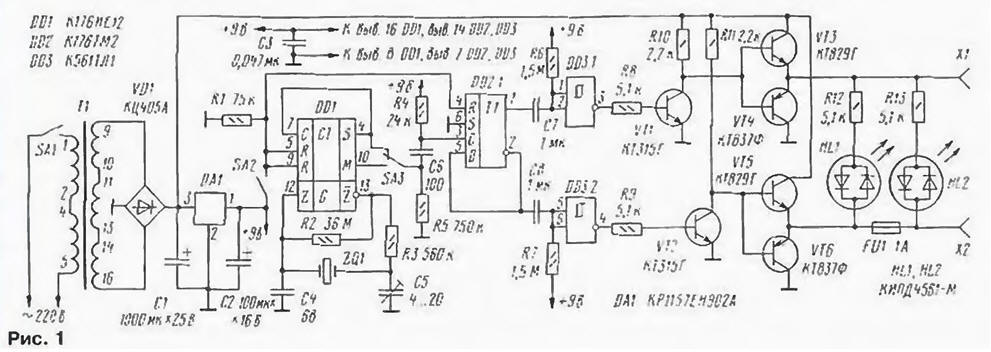
(click to enlarge)
The accuracy of the clock crystal oscillator determines the frequency divider to one pulse per minute on a chip DD1. Through the switch SA3 and differentiating chain C6R5 pulses arrive at the input of the counting trigger DD2.1. The voltage on it the outputs are changed once per minute. The output signals of the trigger differentiated chains C7R6 and C8R7 and converted by a Schmitt trigger DD3.1 and DD3.2 in pulses positive polarity with duration of 1 C. At the end of each minutes at a time turns on the transistor VT1 or VT2. Through two-stroke emitter follower transistors VT3, VT4 and VT5. VT6 pulses the collectors of transistors VT1 and VT2 through the fuse FU1 come on secondary clock.
Thus the stepping motors of the secondary clock pulses with a period of 1 min, an amplitude of about 24, a duration of about 1 s and the evolving every minute of polarity. LEDs HL1 and HL2 indicate work hours. Fuse FU1 protects them from short circuits in the output circuit. When burnout is only activated led HL1.
The asymmetry of the emitter followers transistors VT3 - VT6 - apparent. The transistors VT3 and VT5 are included through resistors R10 and R11 is pretty big resistance, therefore, required the use of a compound series meters CT. The same transistors VT4 and VT6 are included via the included transistors VT1 and VT2. having in a saturated state of low resistance, and in this case it is possible using a conventional transistors series CT.
The switch SA2 is used to accurately start the watch, switch SA3. through which with the exit of DD1 chip serves pulses with a frequency of 1 Hz. provides control the primary work hours and the possibility of an accelerated secondary transfer hours forward. In this case, the pulse duration at the secondary clocks is exactly equal to 1I S.
To start the primary clock manually install all secondary to the nearest whole hour. To close the primary contacts of the switch SA2. the switch SA3 set in the lower according to the scheme position. Then the SA1 toggle-switch include primary clock and check all secondary readings. If any of them show set hour plus 1 min then disconnected from their primary, again set to the same whole hour I. reversing the polarity of the connections again connect to primary.
After 1 s after the sixth signal check time contacts of the switch SA2 open. The state of the trigger DD2.1 does not change. Later, with another 39 on the output M (pin 10) of the chip DD1 appears high logic level, but the state of the trigger DD2.1 remains the same. 1 min after the sixth signal a high level at the output of M will change to low, the resulting voltage drop predifferentiated chain C6R4 and in the form of a short pulse of negative polarity will arrive at the input of the trigger DD2.1. The decline of this pulse will switch the trigger DD2.1 In the absence of the differentiating circuit, the trigger switch would not after 1 min, and after 39 after the switch SA2 that would hinder the start.
Adjust secondary readings hours in the course of their operation following way. In the last minute of the hour when the minute hand of the secondary clock show 59 min. close the contacts of switch SA2. while all watches switch and start showing 00 min. Later 1 after the sixth signal check time open contacts of the switch SA2. that provides accurate start hours.
In the described device is used resistors MLT-0.125 (R1. R3 - R9). MLT-0.25 (R10-RJ3) KIM m (R2). the capacitors C50-29 (CI). K52-1 (C2). CT-256 (C5) and km-6 (the rest). Quartz - watch on the frequency 32768 Hz. transformer - TN. Switches SA1. SA2 and the switch SA3 - any small-sized.
Bridge rectifier CCA can be replaced by any four diode operating current not less than 0.5 A; transistors CTG on any low-structure n-p-n a working voltage of at least 30 V. the Transistors VT3 and VT5 should be an integral the structure of n-p-n series CT. CT, CT. CT with any alphabetic indices. VT4 and VT6 - structure p-n-p is large or average power ratio current transfer not less than 50 - series CT. CT. CT; CT - index, I.e. K. N. S. F.
Chip KRITA interchangeable on 78L09, as well as any stabilizer with with a 9 V or resistor of 2.2 ohms and Zener voltage 8 10 V
When replacing two-color LEDs on the usual exception of the breakdown in reverse direction sequentially with each of them should be included on the silicon the diode at a voltage less than 50 V.
Almost all the details of the primary clock mounted on the PCB size 70 - 90 mm (Fig. 2). the LEDs are soldered to the printed conductors. Board is placed in metal enclosure dimensions 200x100x80 mm on the top panel which placed all other watch parts. The LEDs are brought out through holes in the top panel.
Clock adjust using a digital frequency counter, the input of which is connected to the output S (pin 4) DD1 chip by Setting the frequency in the measurement mode period of pulses with a frequency of fill 10 MHz, trimmer capacitor C5 achieve equality of the period of one second. After two or three weeks of operation the clock corrections. A well-regulated clock ensures accuracy travel is not worse than 2 a month.
Author: S. Biryukov, Moscow