In schemes with a powerful load and high switching frequency to change electromagnetic relays and starters came power semiconductor switches with optical isolation. Currently there are devices allows them to be used in systems with direct control from logical levels chip type TTL, hook up, CMOS, etc.
For AC circuits the preferred chipsets with the inclusion of the electronic key at the time of the passage of the voltage through zero. This eliminates large impulse noise, the occurrence of switching surges due to fantastic shift between current and voltage, and reduces demands on network filters or allows you to do without them.
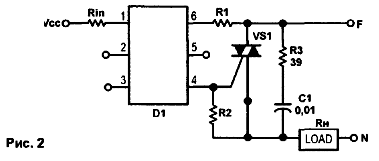
Spontaneous switching power triacs due to random voltage spikes during commutation of the windings solenoid valves or electric motors may cause interfacial circuit. For correct this, use the bypass power outlets damping RC-circuit. When you enable powerful loads at low (near zero) voltage substantially decreases the amplitude of current pulses when dealing with capacitive loads. Except the triacs operate in soft mode and their reliability increases dramatically.
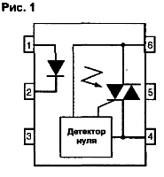
Typical representatives of the contactless power switches are optoisolator MOSM/32M/PPM. MOSM/ 42M/M. MOSM/62M/63M, MOSM/M, MOS/82/83 [1] (a similar description is also with logo Fairchild Semiconductor) manufactured in a 6-pin DlP-housing (Fig.1). They consist of an infrared emitting diode, optically associated with the detector bilateral voltage transition through zero, and the output Optimiser. These elements is easy to use with powerful triac, solid state relay and other industrial controls.

Chips, marking that ends in 1, 2 and 3, provide enabling the load applied to the led current, respectively 15, 10 and 5 mA. The voltage drop across the infrared led is 3 V. the Chip, the penultimate digit of marking that ends in 3,4,6 and 8. designed for switching circuits with a maximum voltage of 250, 400, 600 and 800 V. the Maximum value of the pulse current switching - 1A in ed 100 μs. Maximum continuous switching current - 60 mA.
The switching circuit chips for controlling the triac shown in Fig. 2.

For MOSH/MOSH/ MOSH/MOSH resistance R1 must be accordingly, 180, 360, 360 and 360 Ohms. R2 is 1 kω, 330, 360 and 330 Ohms. Output the current IC can be up to 1 A, but only in the moment of switching of the power triac VS1. therefore, you cannot use this output as burdock, constant loading load. One output can be connected to only one triac.
More powerful triacs can be connected to the chip via an intermediate amplifying the triac.
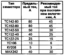
The table shows the recommended triacs for direct connection to devices.

Triacs have to be installed on radiators. Note that operating currents, a circuit-switched triacs, temperature-dependent. Legacy triac type TC 161 require unipolar enable signal to these circuits.
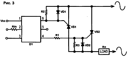
As the power elements instead of triacs can be applied to the thyristors, included counter-parallel (Fig. 3).

The resistor values are chosen in accordance with the recommendations to Fig. 2, diodes - 1 N4001.
In [2] shows the main types and parameters of the modules of the Russian production.
Sources of information
Author: V. Melnik. Dneprodzerzhinsk, Ukraine


