


")

Acoustic relay is connected in series with the load, it engages smoothly, off is performed after a certain period of time. It does not create interference and practically does not reduce the brightness of the lamp filament. In addition, the device has a voltage indication switching off the load and emergency shutdown overcurrent protection. The device is assembled on the circuit Board size 28x50 mm and fits easily into a light switch for internal wiring.
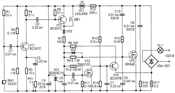
The device is powered by 220 V through the load (incandescent lamp EL1). The power supply voltage is supplied to the diode bridge VD4-VD7 through the terminal. A key element of the device is a field effect transistor VT5 included in the diagonal of the bridge through resistor R17, which is a current sensor. In the initial state, all capacitors are discharged, the voltage between the gate and the source of a field effect transistor VT5 is zero, whereby this transistor is in the closed position. The current through the load is practically absent. The voltage of the source-drain of the transistor VT5 is partially protected from possible surges in the network by capacitor C10. Under the influence of this voltage, the capacitor C4 is charged through resistor R12 and diode HL1 to the reference voltage of the Zener diode VD1 (15).
Signal amplifier with electret microphone WM assembled on the transistor VT1 and running a small collector current is about 0.15 mA. Microphone power through the resistor R1 by a current less than 0.3 mA. The coupling capacitor C1 of the low-capacity suppresses low frequency signals. Sensitivity adjustment is carried out trimming resistor RP1 in the circuit with negative current feedback. The signal amplified to an amplitude of 1…2, through the coupling capacitor C2 is input to a transistor switch, assembled on the transistor VT2. Negative half wave of the signal exceeding the amplitude of 0.6 V, opens the VT2 transistor and through the diode VD2 and current limiting resistor R7 charges the capacitor C5. The same result can be obtained when you press the SB1 button (non-latching). Through the divider R10R11 this voltage is applied to the gate of the low-power field-effect transistor VT3, opens it, closes bipolar transistor VT4. The voltage on the capacitor C5 for a period of approximately 0.5 MS reaches a level slightly lower than the voltage on the capacitor C4. Via high-ohmic resistor R9 begins to charge capacitor C9 connected directly in the circuit of the gate field-effect transistor VT5. Together with the negative feedback circuit C8R15 ensures smooth opening of a field effect transistor VT5. The soft start time is slightly more than 1 and can be varied by selection of the values of resistor R9 or capacitor C8. After opening of the transistor VT5 diagonal of the bridge VD4-VD7 becomes closed, lights on full brightness incandescent lamp EL1.
Voltage drain-source on-state transistor VT5 is a fraction of a volt, stops the current in the circuit R12, HL1, the led goes out and drops to zero the voltage on the capacitor C4. Signal amplifier with microphone transistor VT1 stops working. Capacitors C5, C9 smoothly discharged through the resistors R10, R11.
The transistor VT4 is used to quickly discharge the capacitors C5, C9 and closing of the key transistor VT5 in two cases:
- at the expiration of the exposure time, when the voltage at the gate of a field effect transistor VT5 is approaching the threshold value and the drain voltage appears;
- in case of overcurrent, when negative relatively negative output C4 of the voltage across the resistor R17 exceeds in absolute value the voltage
opening the emitter-base of transistor VT4 (0.6 In).
Field-effect transistor VT3 for closing of the transistor VT4 during soft start, since in the initial state (the transistor VT5 is closed), the transistor VT4 is in the open state, which is created by the voltage drop across the resistors of the divider R13R14. Upon discharge of the capacitors C5, C9 through resistors R10, R11 and a smooth decrease their voltage VT3 transistor should be closed earlier than the voltage on the capacitor C9 reaches the threshold of closing of the transistor VT5. This is ensured by the selection of the resistances of the divider R10R11. Upon reaching the threshold closing VT5 on its drain voltage appears, which, acting through a resistor R13 to the base of transistor VT4, provides a fast discharge of the capacitors C5, C9 through a current limiting resistor R8 and the transition collector-emitter of this transistor.
The transistor VT5 is closed and turns off the load. Begins to glow led HL1 and there is a voltage on the capacitor C4. The device is ready for re-powering. The time from the load to turn it off when the value indicated in the diagram, is about 3 minutes and may be changed by selection of the capacitor C5 or resistances of the resistors R10, R11 in either direction. Capacitor C7 increases the immunity. The device incorporates a small-sized resistors size 1206 (all resistors in the diagram there is no sign of power) and the capacitor size 1206 (S1-Sz, C6, C7). Resistors RIO, R11 - high resistance EJ-13, EJ-14, R17 - wire. The remaining resistors - MLT, S2-23, C1-4 in accordance with the specified capacity. The capacitor C4 and import of oxide on the voltage of at least 25 In the rest of the film capacitors, for example, K73-17, the capacitors C8, C10, for a voltage not less than 400 V. the Diode bridge VD4-VD7 for a voltage of less than 600 V and a current exceeding the rated current for not less than two times.
The Zener diode VD1 - BZX55C15 for a voltage of 15 V can be replaced KSA, diodes VD2, VD3 - 1N4148, instead you can use KD521, KD522 with any letter index. As diode VD2 (prevents discharge of the capacitor C5, C9 across the junction collector-base of transistor VT2, when the voltage on the capacitor C4 drops to zero) it is better to include the transition of the collector-base of transistor S, which has a lower reverse current and allows to slightly increase the exposure time. The key transistor VT5 - IRF840 for a voltage of 500 V and a current of 8 A can be replaced by domestic CPB, KV. When switching the lamp power up to 100 W and the exposure time 3 min, the transistor can be operated without additional heat sink because of its significant heating occurs only during power-up. HL1 led red glow low operating current L-53LSRD. Field-effect transistor VT3 ZVN2120 you can replace its analogue KPA.
Author: A. Believ, Volzhsky, Volgograd region; the Publication: www.cxem.net