If to adjust the load voltage autotransformer is used, then with a sudden increase of the line voltage, the load may fail. The proposed device in such cases will automatically disconnect the load.
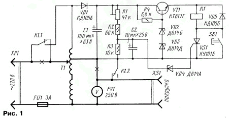
Schematic diagram of the protection device the APR shown in Fig. 1. The scheme of the ATR bold lines and crosses indicate the circuit that must be dropped. The device is powered by winding the Asia-Pacific region through a rectifier diode VD1. On the capacitor C1, the voltage varies in the range 25...55 depending on network. Transistor VT1 is assembled voltage regulator + 22 V.

Resistor R1 set the threshold of the device. If the voltage exceeds set threshold, the Zener diode VD4 appears, therefore, opens and SCR VS1. Relay K1 will work, and the contacts K1.2 turn off the load. In addition, the contacts K1.1 will switch the input voltage to the top circuit output winding. This state of the Asia-Pacific region is not dangerous, since the upper winding rated output for mains voltage up to 250...260 V.
To change to original state, you must first install the required voltage at the output of the Asia-Pacific region by turning the adjustment ring, and then press the SB1. The thyristor VS1 is closed and at the time of releasing the button will trigger the relay by connecting load.
Relay K1 - RAC-1 NF4 CS.569.007. It can be replaced with a voltage other winding to 18, the operating current of 50 mA and two groups of switching contacts for a current of 2 A at AC 250 V, for example, REN-34 passport HP.500.001-01. Transistor VT1 can be series CT, KT807. Diodes VD1 and VD5 - CDV, CDG or series KD, D226. Zener diodes VD2 and VD3 can be replaced one XI, a VD4 - XA, XA. Fixed resistors - MLT, trimmer R1 - GPA-16, the capacitors C1 and C2 - oxide K50-16, K50-35.
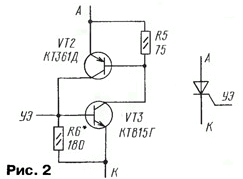
SCR VS1 - series CU with indices B, C, D, E or KU112A. You can replace SCR node of the two transistors, as shown in Fig. 2. Here VT2 suitable transistors series CT, CT, CT, CT, a VT3 - KT315, KT3102. If the operating current of the relay more than 50 mA, the transistors should be more powerful - series CT, CT, CT (VT2) and CT, KT807, KT815, CT (VT3).

The device is placed inside the housing of the APR. When establishing and operating the APR need be very careful, as all circuit device electrically connected to network.
The establishment is to install a resistor R1 threshold of the device. First, the R1 engine is installed in upper circuit position. Connecting in parallel to the load voltmeter, include the Asia-Pacific region in the network. The regulation ring set the output voltage of 230 V. a Screwdriver with a dielectric handle slowly rotate the engine R1 until the relay K1. The delay positives (about 0.5 s) can be increased by the capacitor C2 more capacity. When using the relay trip current of more than 50 mA transistor VT1 must be installed on a heat sink to prevent overheating.
In conclusion, the device can be applied to any of the APR, if there is a drain at 25...30 V AC. In makeshift structures need to wind an additional winding to a voltage of about 25 V. In this case the galvanic connection of the device with the network.
If we exclude the contacts K1.2 by connecting the load directly to the output of the Asia Pacific in an emergency situation, the load will not turn off, but it will decrease the voltage as the input voltage will be applied to all the winding of the Asia-Pacific region.
For reliable operation it is desirable between the control electrode and cathode of the thyristor VS1 to include a resistor of 3 to 10 ohms.
Author: Ilham Aliyev


