


")

The proposed scheme may find application in any devices where you want to restrict access to the switch. Depending on what is connected to the output of the circuit (solenoid, relay, alarm, etc.), the appointment can be very different, such as disabling mode alarm.
In the simplest scenario, together with the electromagnet, the circuit can be used as a code lock. Its opening is made the set is known to a limited circle of persons code. The code consists of 4 digits (from 10 possible). Buttons with certain digits, you must press in the given sequence. This enables you to have not less than 5040 possible variants of the code.
Code easily and quickly can be changed by rearranging the terminal wires with buttons in any sequence. When you install undesirable code take the digits of the serial number(1, 2, 3, 4). Better if the code would be of random numbers, for example: 9, 3, 5, 0.
The scheme code of the device (Fig. 1.38) collected on two microcircuits CMOS series 561 TM2 (possible replacement for TM). providing high reliability and efficiency of operation. Consumption scheme allows microcurrent easy to perform, if needed, self-powered. For get even not stabilized DC voltage of 15 V. 4…
Works electrical circuit as follows. At the initial moment, when power is supplied, the circuit of capacitor C1 and resistor R1 generates a reset pulse triggers (on outputs 1 and 13 of the chip will be log. "0").
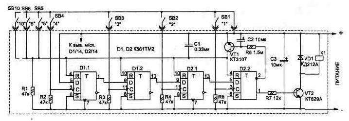
Fig. 1.38
When you press the button the first digit of the code (in the diagram - SB4), at the time of its release the trigger D1.1 switches, i.e., the output D1/1 will log. "1" because the input D1/5 is the log. "1".
When you click the next button, if the input D of the corresponding trigger a log file. "1", i.e., previous work, then log. "1" will appear at its output.
The last trigger D2.2 , and that the scheme left in this condition for a long time, a transistor VT1. It provides delay reset triggers. The delay is made through the circuit to charge the capacitor C2 through the resistor R6. For this reason, the output D2/13 the signal log. "1" will not be present for more than 1 second. This time is sufficient for relay K1 or electromagnet. Time, if desired, can be done easily significantly more by using the capacitor C2 with a larger capacity.
In the recruitment process code press any erroneous figures to reset all the triggers. If the control signal of the transistor VT1 to remove from the output not the last trigger (for example with D2 o/12), will be limited to necessary time to press a digit code. In this case, even if correct, but slow the code output will not appear.
Is the scheme near the keypad.
All used items, with the exception of the transistor VT2 can be of any type. The VT2 transistor is applied with great odds gain, and in the case of use as a load instead of electromagnet relays needs to be replaced by more powerful from CT.
To open the latch door lock is best to use not the electromagnet and electric motor with a reducer. Such nodes are used in part of car alarm systems to automatically lock the doors (their you can buy in the store). They consume a small current (60…150 mA 12 In) compared with the electromagnet and allow you to have a power source small power, which is especially important for Autonomous power supply.
Publication: www.cxem.net