A significant drawback of the widespread submersible vibration water pump "the Kid" - the sharp dependence of its performance from the supply voltage. Dangerous for him and the work of "dry" - current consumption significantly increases and the pump fails. Author of published articles was able to find the solution to these problems.
In many rural and suburban networks of power supply voltage is very different from a nominal 220 V, usually downwards. And operational practice pump "Kid" shows that at a voltage of less than 190 In the rise of water from wells is no longer possible. There is a way to increase and stabilize the performance of the pump. This requires maintaining a constant it will consume current regardless of the supply voltage.
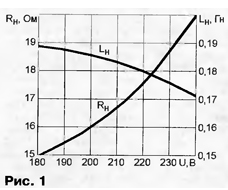
Equivalent circuit of a pump can be represented by series connected inductance Ls and resistance RL. Both values, as shown in charts of Fig. 1, depend non-linearly on the voltage, making RL=17.5 Ω, Ls=0,18 GN (inductive reactance at the frequency of 50 Hz - 56,1 Ω) at a voltage of 220 V. Nominal current pump Ls=3,75 A.

To increase the current in the circuit of the pump to a nominal low voltage, having compensated a portion of the inductive reactance capacitive. It is enough to include in series with the pump capacitor C1, as shown in Fig. 2.

It reactance Xc1 must be equal:

and capacity

where U is the voltage in the network.
Calculations show that with fluctuations in the mains voltage in the range 190...240 In the capacitance of the capacitor C1 should be changed from 30,1 to 27.9 UF. To do this manually is very inconvenient and unexpected increase in voltage may cause the output of pump failure. So, using the considered method makes sense only at low, but constant mains voltage. The capacitor must be designed for a voltage of at least 500 and is shunted by the resistor 100...200 kω. It is unacceptable to use oxide capacitors.
To maintain the current of the pump is constant when the voltage fluctuations is possible by connecting parallel to the capacitor C1, the inductor L1 with a steel magnetic core it is shown in Fig. 3.

Since a current flowing through the capacitor and the inductor, anti-phase, flows through the pump their difference:
IR = IC-IL
Due to the saturation of the magnetic circuit reactance of the inductor depends on of the applied voltage. The total resistance of the circuit L1C1 is also changed, being capacitive and supporting the current of the pump is approximately equal to the nominal.
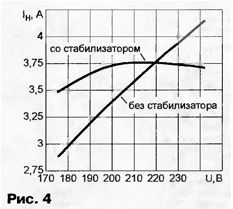
For better stabilization of the capacitance of the capacitor C1 should be selected on 10... 15% more calculated by the above formula for the minimum voltage U, the parameters of the inductor L1 to pick up experimentally. The author has used the set metal film capacitors with a total capacity of 33.3 UF voltage of 600 V. The throttle - 1500 turns of wire sew-2 0,8 on the yoke SLM 25x25 mm. In Fig. 4 shows dependence on the mains voltage and current consumed by the pump "The kid" with the stabilizer according to the scheme of Fig. 3 without it.

In some situations, the current consumption vibration pump, could exceed valid value even in the presence of the stabilizer. So it happens, for example, when water in the tank where it is pumped out, no longer exists, but the pump continues to work "dry". If you miss this point, the output of the pump failure is inevitable.
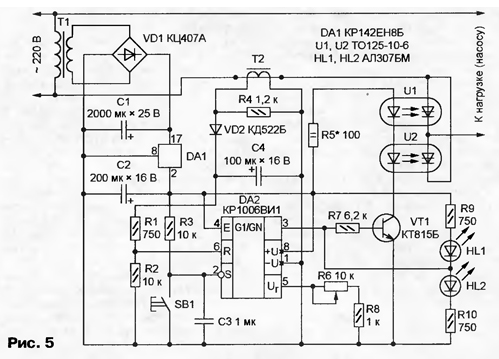
Device, scheme of which is shown in Fig. 5, will serve as a kind of watchdog, disconnecting the pump from the mains in excess of the allowable current.

When appropriate adjusting the threshold you can not follow the rest of water. When she over, the pump will be turned off automatically. This feature is especially important when pumping water out of idle wells and reservoirs.
"Watchman" is made based on the integral timer CREW and works as way. In series with the load (pump with or without stabilizer) included electronic key on obliterator U1 and U2 and the primary winding current transformer T2, the secondary winding of which is loaded by a resistor R4. The secondary winding voltage, proportional to load current, the diode rectifies VD2 and a smoothing capacitor C4. Through a resistive divider R1R2 part of it goes to pin 6 DA2 - direct entry of one of the available on-chip Comparators. At its inverted input receives exemplary tension set series-connected resistors R6 and R8. The power source of the chip DA2 made by the standard procedure on the elements T1, VD1, C1, C2 and DA1.
When the device in the network chain R3C3 generates a pulse setting an internal trigger circuit in DA2 a condition in which the output 3 - log. 1. Transistor VT1 is open, the LEDs of photothyristors U1 and U2 the current flows, electronic key connects the load to the network. Lighted led HL2.
If the load current increases to the value at which the voltage at pin 6 DA2 exceeds exemplary, the comparator inside the IC is triggered, and the trigger will change state. Transistor VT1 electronic key will be closed, cutting off electricity to the load. Led HL2 is out, a HL1 will begin to glow. Re-enable the load can clicking on the button SB1, which will drop the trigger circuit DA2 in the source state.
The current transformer T2 is made from any power transformer 10 to 20 watts. All available secondary winding of the transformer is removed and replaced stranded insulated Assembly wire cross section of at least 1 mm2 wound one new, with the number of turns 400...600 times smaller than in a network. New winding becomes primary (it is included in series in the load circuit), in the former the network is secondary. The work of the current transformer without a load resistor R4 invalid.
When establishing a "guard" instead of the pump "the Kid" is desirable to use a different load, for example, electric cooker with adjustable power burners. In adjusted the device voltage at pin 5 of chip DA2 has a little to exceed the voltage at its pin 6 at the rated load current (pump). The input impedance of the measuring devices connected to the terminals DA2, should to be not less than 100 ohms.
To verify the correctness of the adjustment, the pump is immersed in water in a small depth, include and expect when it is above the water level. Automatic pump switch-off should occur after 1...5 seconds.
The calculation of the stabilizer for vibration pump
Author: B. Porography, Krasnoyarsk


