


")

In the logs shows a lot of schemes for independent the manufacture of similar utility devices, however, as experience shows, the greatest difficulty in the manufacture of such devices is the high-voltage winding coil so that there is no breakdown inside of her, and manufacturer beautiful case. The flow chart below and the design is easy to solve these problems.
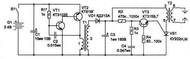
Fig. 1.24
The electrical circuit (Fig. 1.24) contains only unified and easily accessible items, including high voltage coil T2, which is applied to the transformer line scan from black and white miniature TVs TVs-P.
The proposed scheme allows to remove the dependence of the voltage supplied to the high voltage coil from the threshold dynistor (their most often used, as it is implemented in previously published schemes.
The circuit consists of oscillator transistors VT1 and VT2, which increases the voltage to 120…160 using the transformer T1 and the drive circuit of the thyristor VS1 on the elements VT3, C4, R2, R3, R4. Accumulated condenser NW energy discharges through the winding of T2 and an open thyristor.
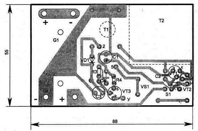
Fig. 1.25
Transformer T1 is made on a ferrite ring the yoke MNM size Chj,5 mm. Coil 1 contains 10 turns, 2 - 650 turns of wire PELSHO was 0.12. Capacitors: C1, Sz type K50-35; C2, C4 type K10-7 or similar small-sized. Diode VD1 can replace KDA, B. S1 - microcluster type PD-9-2. The thyristor can be used anyone with a working voltage of 200 V. the Transformers T1 and T2 are attached to the Board with glue.
The printed circuit Board device has dimensions h mm (see Fig. 1.25).
The whole scheme together with two batteries A316 or batteries Nkgts-0,45 fits easily in a pack of cigarette hard frame (type-CAPITAL) (Fig. 1.26).
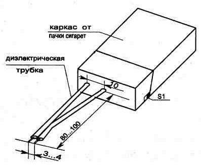
Fig. 1.26. Design corps
The discharge chamber is located between two rigid wires with a diameter of 1…2 mm at a distance of 80…100 mm from the case. The spark between the electrode is held at a distance of 3…4 mm.
The circuit consumes less than 180 mA, and resource elements power enough for more than two hours of continuous operation, however, is not discontinuous to use the device for more than one minute are not desirable because of possible overheating transistor VT2 (it has no radiator).
When you configure a device may require the selection of elements R1 and C2, and the change of polarity winding 2 of the transformer T1. It is also desirable to carry out the adjustment with an unidentified R2: check the voltage on the capacitor Sz voltmeter, and then set the resistor R2 and by controlling the voltage on the oscilloscope anode of the thyristor VS1, to ensure that the discharge process of the capacitor CP.
The NW discharge through the winding of transformer T2 is happening with the opening of the thyristor. A short pulse for opening the thyristor is formed transistor VT3 with increasing voltage on the capacitor Sz 120V max.
The device may find other uses, for example, as an air ionizer or a stun (frightening) device as between the electrodes of a spark gap, there is a voltage over 10 kV, which is quite enough for the formation of an electric arc. At low current in the circuit is the voltage not life-threatening.
Publication: www.cxem.net