


")

The operation of certain electrical appliances may be useful the device forming time cycles on and off. Author applies it with submersible pumps brands "Baby" and "Brook", but it is useful for cyclic defrost refrigerator and in other cases.
Schematic diagram of the machine shown in Fig. 1. It consists of a divider the network frequency of the shaper time intervals, actuators and indicator.
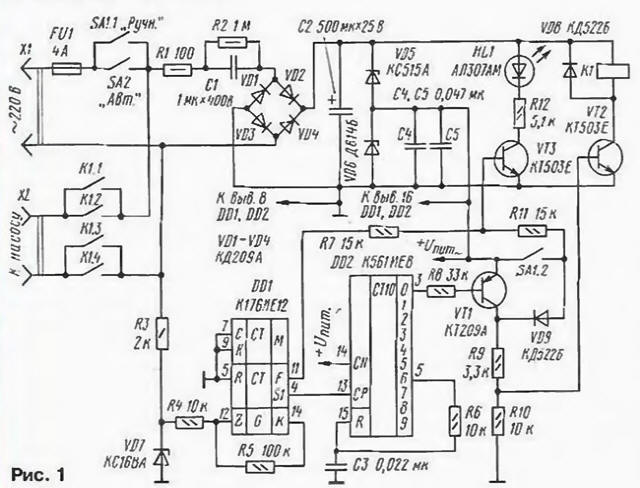
The frequency divider implemented on the chip CIE [1] (DD1). At its clock input do limited chain R3VD7 the positive half of the mains voltage, of which two inverters circuits DD1 and chain R4R5 are formed rectangular pulses. Output divider (vyv. 4 chip DDI) pulses have a repetition period 655 C (or 10 min 55 s). This time interval specifies the duration of the pause; the length of the operating cycle is defined the multiplier chip DD2 [2]. When specified in the scheme to enable this coefficient is equal to six, i.e. one period of the pause has five working periods with a total duration of 54 min 36 s, during which the pump will be included. The circuit for initial installation of counters in order to simplify the scheme is not provided.
The actuator is formed by an inverter at the transistor VT1. the key to the transistor OUT and relay K1. when triggered, which closes the contacts To 1.1 - To 1.4 connecting the pump to the network. When in automatic mode, the pulses voltage with a period of repetition of 0.64 with the pin. 11 DD1 chip through a resistor R7 arrive at the base of the transistor VT3 I. periodically opening it. make flashing led HL1.
To turn on the pump manually, use the toggle switch SA1. With the closure of its contact SA1.2 transistors VT2, VT3 open, the relay is activated and its contacts connect the pump to the network. In this mode through the led HL1 will leak DC, and it will Shine steady.
To power the machine is applied to the source with the ballast capacitor C1, rectifier diodes VD1 - VD4 and the stabilizer on the Zener diodes VD5, VD6.
The machine is mounted on a printed circuit Board of foiled fiberglass (Fig. 2). When assembling the used resistors MLT-0,5 (R1 and R2J and MLT-0.125 (the rest). Capacitor C1 - K73-17 (and any other with a specified capacity and allowable voltage not less than 400 V); C2 - C50-6 (working voltage not must be less than the total voltage stabilization circuit VD5. VD6); else - K10-7, km-6. Chip KIE can be substituted from the series C, 564. As VT1 will fit any low-power p-n-p transistor, and VT2 and VT3 needs to be the extra-Shamim voltage IKE not less than 30 V. Vibramycine diodes VD1 - VD4 must have a valid reverse voltage over 300 V; led - any type. The desired brightness of its light can be set by selection of resistor R12.
Switches SA1, SA2 - any toggle switches with two sets of contacts, allowing switching voltage 250 V at currents up to 2 A (for example. TP1 -2). Relay K1 - RES passport RF4.500.163. You can apply relay of a different type, but it can to need replacement of the Zener diode VD5 with the working voltage of the relay coil. For example, when using a relay with a coil voltage of 12 V Zener diode XA (VD5) should be replaced by XA. The relay contacts in either case should to be designed for switching mains voltage at currents up to 2 A.
The device is mounted in body size 150x80x40 mm. On the end the surface of the casing, the switches and the led. Fully assembled the machine should be fixed on the body of the hydrant or other convenient to use, excluding water entering the device.
Correctly assembled device begins to work immediately after switching on; the divider on the chip DD1 in automatic mode controlled by blinking led KL1.
On the basis of the described device can be made and the devices for other purposes, for example, automatic defrosting of the refrigerator and several others. In this case you may need to change the ratio of the pulse duration and pause at the expense of use different outputs of the counter DD2. So if you connect a resistor R6 to output 2 (pin. 4 DD2) implemented a 1:1 relationship. to output 3 (pin. 7 DD2) - 2:1 and etc. With the greatest possible respect 9I chain R6C3 should be deleted and conclusion 15 DD2 to connect a common wire. To change the division ratio of you can install a switch that connects a resistor R6 to one or another outlet counter DD2.
The order of operation of the device, it is possible to do the opposite (in this case, the working pulses will be several times shorter than the pauses). For this purpose, the transistor VT1 should be replaced the transistor structure of the n-p-n, for example, on any series KT315 or C. included the emitter follower (collector - to-chain +u pit, the emitter - to R9, VD9). Timings will remain the same.
You can also cut all the cycles in half, connecting pin 13 DD2 not to conclusion 4. and the pin 6 of the chip DD1. The pause duration will be 5 min 28 S. will change accordingly and the length of the operating cycle.
ATTENTION! The machine has a transformerless, so when it is testing and installation should be very careful. Metal the machine case should be grounded (connected with the housing standpipes). Better to use a plastic housing. The supply circuit must be such stateroute a manner that the circuit through the switches connected to the phase the wire network. Common wire of the device should not connect with his body.
Literature
Author: Dmitry Nikishin, Kaluga