


")

To improve the STINOL refrigerator-104 author made household trouble is the second time in five years of operation has failed the thermoregulator. To buy a new one to install it yourself, no failed - the device is sold at unacceptable price, including the cost install. We offer our readers a homemade device not just replaces the regular thermostat. Includes extras, designed to protect the refrigerator in many emergency situations that are occurring around the time of operation.
The weak point of all compressor refrigerators - overloading of the motor, powering the compressor, when it is repeated after a short time after stop enabling. The cause of the overload is quite long-lived the condenser of the cooling unit high-pressure refrigerant.
The manual for fridge STINOL requires that the duration shutter speed between switching off and switching on again the compressor was not less than 3 min. But typical today unexpected shutdowns and re-inclusions of electricity to meet this requirement, not a "calling on" electronics, not possible.
To protect the motor in the refrigerator there is a thermal relay. Usually it combined with starting relay and is called the start-up and protection [1]. However, the practice proof of the inefficiency of such protection.
Like any other appliance, the refrigerator is useful to protect against significant deviations of voltage from a nominal 220 V. a Large number of publications on this topic (e.g., [2, 3]) indicates the urgency of the problems in rural areas and in big cities.
The proposed control unit performs the following functions:
- turning on and off the compressor in the refrigerating chamber set temperature, replacing regular thermostat, and there is a possibility to adjust the hysteresis is the temperature difference between on and off compressor;
- forcibly turns off the compressor when a significant voltage deviation in the network from the norm;
- prevents reclosing of the compressor earlier than 5 min after switching on any reason, including due to the deviation of the mains voltage from norms or initiated by the thermostat. The latter is particularly important, as dangerous situation easily provoked, immediately after the compressor is turned off sharply turning the temperature regulator toward lower or opening the door the refrigerating chamber.
Provides indication of the status of the control unit LEDs "Work" (compressor on), Pause (compressor off), Lock (not expired a five-minute ban), "<" (the line voltage is below the minimum valid), ">" (the line voltage is above the maximum allowed).
The block diagram shown in Fig. 1. It consists of a node controller on the chip DA2, on-delay timer transistor VT1 and the elements DD1.1, DD1.2, the control node of the voltage on the elements DD1.3, DD1.4 and the chip DD2, actuators transistors VT2, VT3.
(click to enlarge)
Connected in parallel to the relay contacts K1 are included in the circuit of the compressor motor instead of regular contacts of the thermostat of the refrigerator.
The node power supply consists of transformer T1, rectifier (diode bridge VD1) and integral stabilizer DA1 voltage of 9 V.
To change the load on the rectifier when triggered and released, the relay K1 is not affect the operation of the node control voltage, a resistor R27, plug the transistor VT3 to the rectifier, when the relay coil is de-energized. The resistance of the resistor equals the resistance winding of the relay, so consumed from the rectifier current remains unchanged.
For example, the block included in the network at a nominal voltage of 220 V and a node control voltage has no effect on his work. Transistor VT1 is closed, the capacitor C2 is discharged, the logic level at the exit of the element DD1.2 low, diode VD3 is open, so the thermostat on the OU DA2 locked in a state the corresponding low temperature in the refrigerating chamber, therefore, off the compressor. Transistor VT2 is closed, relay K1 is de-energized. Burn LEDs HL1 "Lock" and HL5 "Pause".
5 minutes after charging of the capacitor C2 through the resistor R2 to the threshold switching of the Schmitt trigger on the elements DD1.1, DD1.2 output level the latter becomes high, diode VD3 is closed and the thermostat will receive the opportunity to work. HL1 led will go out.
With the increase of temperature in the refrigerating chamber, the resistance of the thermistor and RK1 the voltage drop is reduced. If the temperature is such that the voltage the inverting input of op-amp DA2 less than noninverting, output level OU - high, which leads to the opening of the transistor VT2 and tripping relays K1, including the compressor. The HL4 led lights, HL5 - no.
With decreasing temperature in the refrigerating chamber, the voltage at inverting input The OS is growing, which in turn changes the state of the OS and turn off the compressor. The HL4 led goes out, HL5 - lit.
The voltage drop at the collector of transistor VT2 at the moment of release relay causes the charging of capacitor C6 and short (20 MS) opening transistor VT1 pulse of charging current. Discharged through the opened transistor capacitor C2 again, as after connecting the unit to the network, starts slowly recharge, resulting in a five-minute ban on the compressor. VD2 diode protects the emitter junction of transistor VT1 negative impulse from upon discharge of the capacitor C6 through the opened at the moment of switching relay K1 transistor VT2.
The desired temperature in the refrigerating chamber is adjusted with the variable resistor R16. The width of the hysteresis loop of a temperature regulator to regulate a variable resistor R20. The need to change the hysteresis in the operation controversial, however, during the initial adjustment can not do without it. Hysteresis must be sufficient to ensure that the compressor does not turn on too often, and in the intervals of his work, the wall temperature of the refrigerating chamber reached positive values and they formed the frost melted, not accumulate.
Consider the node of the control voltage. If it is in the acceptable range, the voltage at the inputs of the element DD1.3 below, and on inputs element DD2.1 above the threshold of switching. Levels at both inputs of the element DD2.3 high and its output low, giving the opportunity to all other nodes unit to operate as described above.
When the voltage is less valid element DD2.1 change state. The logic level at its output will be high, this will be the outputs elements DD2.3, DD2.4. The HL3 led will be lit and the transistor VT1, outdoor the voltage supplied to its base through resistor R19, to drain the capacitor S2, what will block the compressor. With the restoration of normal voltage the HL3 led turns off, the transistor VT1 is closed and through the necessary charging of capacitor C2 will be allowed to work the thermostat.
When voltage exceeding the low level at the output of the element DD1.3 will install a high at the outputs of the elements DD1.4 and DD2.3. Further everything is the same as in the low voltage, only instead of the led HL3 glows HL2.
The values of the network voltage which triggers a protection, it is recommended set is $ 242 (trimming resistor R5) and 187 (trimpot resistor R6).
A break in the supply of electricity the unit will perceive as an unacceptable decrease voltage. It is important that repeated actuation of the compressor was banned if the break duration exceeded required to stop. However, the reaction is not must be too fast and will increase the likelihood of false positives (for example, caused by the inclusion in the same powerful network appliances).
The response time of the described product are after a sudden reduction the voltage is approximately 65 MS - consists of required discharge of the capacitor C1 to a voltage corresponding to the valid minimum and time of discharge of capacitor C2 through the opened transistor VT1. The reaction time on stepwise increase of voltage less than - 25…40 MS. It consumed for charging the capacitor C1 to the set threshold and discharge of the capacitor C2.
All of the elements of the control unit, with the exception of relay K1, variable resistors R16 and R20, thermistor RK1 and fuse FU1 posted on unilateral printed circuit Board (Fig. 2).
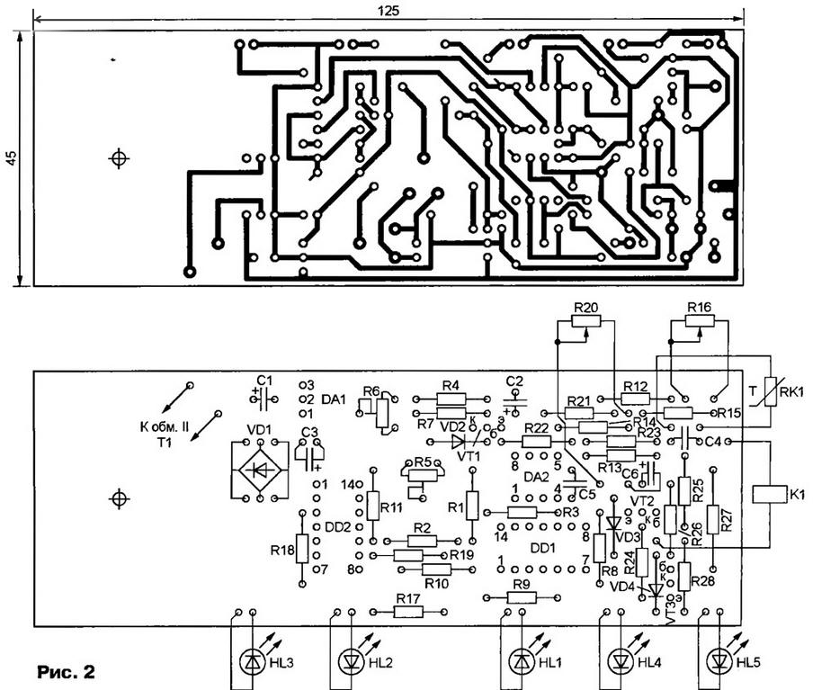
(click to enlarge)
Capacitors 04, C5 - km-6 or other ceramic, other - oxide imported, and the capacitor C2 - series LL (low leakage current). Valid the voltage of the capacitors C1 and C6 (25) is selected with a reserve in case of emergency increase voltage.
Trimmer resistors R5 and R6 - JS4-1, constant - MLT. Variable resistors R16 and R20 - SDR-12 linear (A) the dependence of the resistance on the angle of rotation shaft. The main criterion in favor of a choice of these resistors was that the thread on their mounting sleeve same as a regular thermostat refrigerator.
LEDs HL1 - HL3 - red, a HL4 and HL5 - green glow. Except indicated in the diagram, other LEDs, including domestic production, of suitable size and color of the glow. The chip can KRUA replace CRUD or CRUD.
The transformer T1 should choose a small height, so that it can be to place in the instrument compartment of the refrigerator (see below). The author applies a ready a transformer having a diameter of 40 and a height of 28 mm on a toroidal magnetic core with a secondary winding 12 V at a current of 0.3 A. From commercially available suitable for example, transformers TP-321 -5 and TPC-22.
Note that in the emergency mode, the line voltage is sometimes rises to 380 V. it happens, such as breakage of the neutral conductor of the mains cable. If the transformer T1, unable to withstand such voltage fails, it's not will lead to undesirable in this situation the inclusion of expensive compressor. To protect the transformer from fire is designed fuse FU1 (IT-1). The quality should pay special attention and in any case not replace surrogate.
Thermistor - MMT-1 MMT-4. If its nominal impedance is different from the diagram, you need as many times to change the value of the resistor R12. However, the use of the thermistor resistance more than 3…4 ohms is not worth it worsen the immunity of the thermostat.
Relay K1 - RP-21-004 with a coil for 24 VDC. The audit showed that for its actuation enough and 12, and At 16 V relay works quite reliably. You can use other relays, for example, RENTS. When selecting replacement should pay special attention to the capacity of the relay contacts to withstand the starting current of the compressor, up to several amps.
Mounted circuit Board and the relay K1 is placed inside the utility compartment in the top of the refrigerator. Connected in parallel to the relay contacts connect in the contact group established thermostat. His second a contact group that is used to turn off the fridge for long time, replace the jumper. Now the fridge can be disconnected from the network only one way - by removing the plug from the outlet. According to the author, it provides the greatest safety in maintenance and repair works.
In a unified the front of the compartment has holes for two of thermostats. However, the second there is only one compressor the fridge, in the conventional filter, it is convenient to set the variable resistor R20. Variable resistor R16 is set to a remote location staff thermostat.
In the front panel of the utility compartment have to drill five more holes in are mounted on the circuit Board of the control unit LEDs. Next to them the panel can be applied explanatory notes.
The conclusions of the primary winding of the transformer T1 (one of them is through soldered in a broken wire FU1 fuse-link) connected to the network with wires going in the fridge to the lamp-on indicator.
Shielded wire connecting the temperature sensor is a thermistor RK1 - the Board control unit, placed in an insulating, for example, PVC up and laid on the track remote metal tube of the bellows staffing thermostat. The thermistor installed within the refrigerating chamber there, the end of the bellows tube. It needs to be well insulated and protected from humidity and frost.
The establishment of the control unit, start with the adjustment of the control network node voltage. To do this, using an adjustable autotransformer (Lattre) lower the voltage to V. 187 Rotating engine tuning resistor R6, achieve unstable luminescence ("blink") led HL3. Then increase the voltage to 242 In a similar manner regulate the trimmer R5, focusing on the led status of HL2. After adjusting the sliders of trimming resistors you should lock the nitro.
Further, by disconnecting the unit from the network, translate variable resistor R16 to the position minimum, a R20 - maximum resistance. Set (using Latr) mains voltage equal to 220 and include In the block. Must light up LEDs HL1 and HL5, after about 5 min HL1 led needs out. The duration of illumination and lock the compressor during start-up the need for change, selecting the resistor R2.
To facilitate further adjustment of the inputs of the element DD1.1 (findings 8, 9) temporarily connect a jumper wire with chain +9 V, for example, the output 14 of the chip DD1. The thermistor RK1 immersed in melting ice. After stabilization of his the temperature gradually increases a resistance of the variable resistor R16, ensuring the operation of the relay K1, the ignition of the led HL4 and extinction HL5. The reverse switch should occur with a small decrease in the resistance resistor R16.
The hysteresis (difference of positions of the engine variable resistor R16 when triggered and released, the relays) must grow with the decrease of the resistance variable resistor R20. Once the scan previously installed a temporary jumper removed.
Before turning on the refrigerator with a new control unit engine variables resistors R16 and R20 set in the middle position. Giving the fridge work sufficient to stabilize the temperature of the time, you should make sure that the frost formed on the rear wall of the refrigerating chamber during compressor operation thaws in the pause. If not, variable resistor R20 to increase the hysteresis.
The average temperature in the chamber change a variable resistor R16. If using variable resistors temperature can not be achieved, should pick up the resistors R14 and R15.
In some refrigerators automatic defrost freezer camera every 8 to 10 hours of work automation enforces the compressor for some time, during which work specifically installed heating elements. In this mode, the compressor does not work even when triggered, the relay K1 and the burning HL4 led. This situation should not be to be confused with arise in the operation of the thermal relay motor protection compressor, in which the same signs. To distinguish between "planned" shutdown compressor alarm is quite simple. In the latter case, mounted in the freezer fan will continue to run (with door closed).
The unit can be installed in a compressor refrigerators other models by changing given their characteristics, the placement of the temperature sensor, the control and indication and, if necessary, and the dimensions of the PCB.
Removing elements thermostat is a thermistor RK1, chip DA2, diode VD3, resistors R12-R16, R20, R21, capacitors C4, C5 and connecting the left under the scheme the output resistor R23 to the output of the element DD1.2, the unit can be used to protect all appliances from the mains fluctuations.
Literature
Author: A. Moskvin, Ekaterinburg