Solenoid valves in water supply systems to prevent potential flooding of apartments, basements or other storage spaces, while, unfortunately, not widely used and everyday life. This is partly due to the fact that the time electromagnet energized is not limited, which may result in the output out failure or even fire. In this connection it is of interest offer the electronic control system of the solenoid valve, which, in the opinion the author, avoids such hassles.
A distinctive feature of the described device is very small their consumption of current from the power source in operation, when the valve is open. This enables the use of Autonomous energy source for for a long period of time.
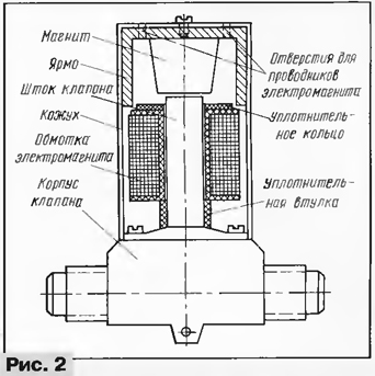
Diagram of the system operation of the electromagnetic valve shown in Fig. 1, and a modified construction of the valve in Fig. 2. The system operation principle is based on the interaction of the fields of a solenoid valve and an accompanying permanent magnet.

(click to enlarge)

The device consists of four functional blocks purpose: alerter humidity, timer electromagnetic relay at the output, voltage Converter power supply and control unit solenoid valve. To valve to enable, press the button SB1 and hold it in this condition 4...5 C. this time, the closed contacts SB1.1 button is connected to a power source voltage Converter, assembled on the elements of the chip DD2. Output multiplier of 3, formed by diodes VD2 - VD5 and capacitors C7 - C10, the voltage increased to 27 In flowing via the contacts SB1.4 on the capacitor C11 and charges it. After 4...5 when the capacitor accumulates energy, sufficient to enable the solenoid valve Y1, release button needs to be released.
Charged capacitor C11 is discharged to the solenoid valve through the contacts SB1.3. Around it a magnetic field which moves the spool in stock valve, and it opens. When the electromagnetic field stops, the spool will keep the magnetic field of the permanent magnet. In the open state of the valve can be indefinitely long time, not consuming energy from the power source until the contacts of the sensor connected to the entrance of the detector humidity, will not get wet.
The elements DD1.1 and DD1.2, the pulse generator, assembled on the elements DD1.3, DD1.4, SCR VS1 and, of course, the sensor mounted on the test point humidity, form a humidity detector. HL1 led connected to the output pulse generator indicates the presence of moisture by periodic outbreaks. Their frequency (approximately 1 Hz) depends on the values of resistor R3 and capacitor C2.
When triggered alarm humidity voltage power source through outdoor SCR VS1 and contacts SB1.2 the starter button goes to integral timer DA1 and the sensor trigger, the function of which performs the transistor VT1. In the base circuit of the transistor a current which charges the capacitor C3 and opens the transistor at the time indicated options chains C3R5. A pulse of negative polarity to the collector transistor VT1 is input to the integral timer DA1 and runs it. When this output of the timer appears the voltage is high, resulting in the led turns on HL2, the VT2 transistor and relay K1 on the time determined by the values of timing chain C4R8. Now through the closed contacts of relay K1.1 the energy of the power source comes on again a voltage Converter, but charging the capacitor C12 through the contacts SB1.3 the starter button, the contacts K1.2 relay and the coil of the solenoid valve.
After 4...5 with the timer switches to its initial state, the relay coil K1 abastecida and the capacitor C12 is discharged to the solenoid valve Y1 through the relay contacts K1.3, but now in the opposite direction with respect to the discharge capacitor C11. There is a counteracting magnetic fields, and the valve stem the valve under the influence of the spring will block the water.
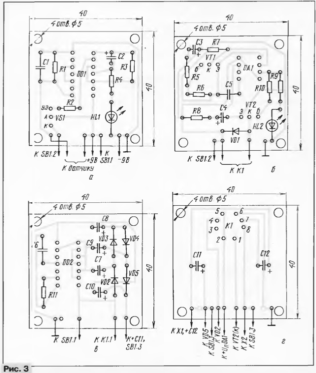
Details units are mounted on four independent boards dimensions 40x40 mm (Fig. 3), made of one-sided glass fiberglass thickness of 2 mm. All resistors - MLT-0,125. Capacitors C3, C4 and C7 - C12 - oxide K50-6, and C1, C2, C5 and C6 - km, KLS. Diodes VD2 - VD5 - the germanium series D311, GD. Relay K1 - RAS (passport RS4.524.202). The switch SB1 - P2K-latched in the depressed position.

(click to enlarge)
Solenoid valve designed for direct voltage 24 V, preferably apply for industrial production, for example, the automatic valve from washing machine "Vyatka". Fit and improvised design that opens the water when voltage is applied to the coil of the electromagnet of the valve. The revision ready the electromagnetic valve is in the complement of its magnetic system and the manufacture of thin-walled cylindrical casing made of duralumin or other non-magnetic material. The magnetic system shown in Fig. 2, can be from drivers direct radiation GD-48-140 (GOST 9010 - 78), pre-released from the flange and core. The magnet yoke is attached inside casing with screws or glue. In the casing to drill two holes for conductors the winding of the electromagnet, after which construction is mounted on the valve stem.
The humidity sensor consists of two metal rod with a length of 10 mm, isolated from one another, which connect to the input of the detector cuts thin stranded wire with the insulation length of 5 m. To the detector is permissible to connect several sensors in parallel and positioning them in different places of the room.
Capacitor C1 protects the detector from interference of electromagnetic radiation, induced in the connecting wires of the sensor with the alarm.
To power the device, you can use low-power AC working together with battery "Corundum" or 7D battery-0,125 in buffer mode, or two batteries 3336, connecting them in series.
The current consumed by the device is so small that the source of the two batteries 3336 will work in the entire duration of their storage.
Establishing device is reduced to selection of capacitor C4 and resistor R8 in the input circuit of timer DA1 so that the capacitor C12 enough time accumulate enough energy required to turn the valve. 4...5 with it needs charged up to the voltage 22 V. 20...
With proper detail and error-free installation the device is ready for operation. But if after power up, the valve will not open, it will indicate the need swap the connection conductors of the electromagnet on the connectors X1 and x2.
Valve mounted on the pipeline in a horizontal position.
It should be noted that the valve of this design can be used for automatic watering of the beds in gardening or agriculture or gardening to create on its basis the regulator of the water level in the tank of the water tower.
Author: A. Burtsev, Novorossiysk


