


")

The use of modern components, in particular microcontrollers reduces the weight and size of electronic devices, to increase the number their functions. The article told about the module code castle made using PIC controller.
The device is intended for use as a site of secrecy (e castle "larvae") in code locks, control systems, alarms or other devices, access to which you want to restrict or fully in some modes.
The module provides the appearance of a high logic level at its output when the keyboard seven-digit decimal code. When its repeated the set that results in a low level. In the structure of the module - two independent apart channels, each of them controls one output. Access codes in the channel can be set (modified) by the user in a special mode PE. In the channel moves when dialing with seven-digit keypad code presets (each channel has its own code). From this mode, you to modify how the access code and the preset code. All codes for both channels are stored in an electrically programmable memory data (ЕЕРROM) module, which is writable by software.
Diagram of the module shown in Fig. 1. It is based on a PIC16F84 microcontroller company MICROCHIP, which ensures low power consumption and minimum cost [1]. All functions implemented in software. The port pins In the microcontroller DD1 (RBO- RB6) are used to connect a standard 12-button keypad. RB0-RB3 programmed to input data, a RB4-RB6 - on conclusion. Conclusion RB7, programmed as an output, is used for the supply of audio signals.
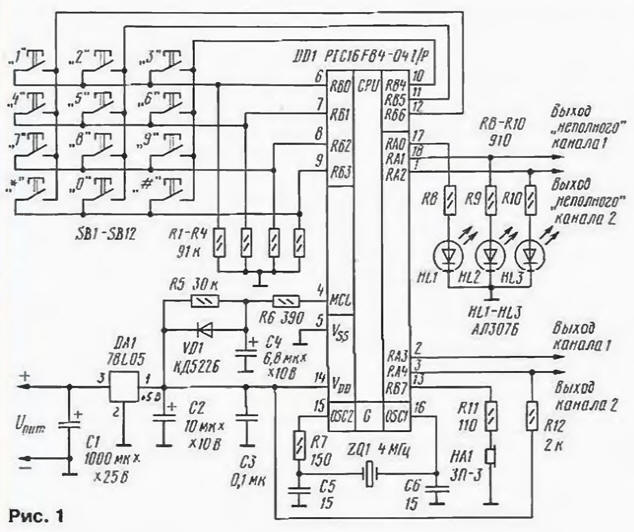
Each time you press any key, which is detected and evaluated as a "true" output DD1 13 you receive a pack of 124 pulses with the period between them is about 4 MS. Sounds a short beep. While holding keys packs follow each other without a pause (constant signal). When typing the correct code (access or PE) this pin appear 1240 these pulses (the beep sound lasting about 5 seconds).
Elements R5, R6, C4, VD1 made a site external reset of the microcontroller when power-up. The port pins And the microcontroller RAO - RA4 programmed as outputs. RAO is the flag resolution preset mode for both channels. Setting this flag (resolution preset mode) is indicated with a led HL1. Flag is set when you press the button "*" the keyboard, and reset when you press "#" or at the end modification codes in the preset mode in any channel or system at the time reset (off-power).
RA1 and RA2 - flags of the preset modes channels 1 and 2. Each of them is set when the corresponding code set preset, but is reset when you press the "#" or after modification codes in mode preset in the corresponding channel or after a system reset. Installation each of these flags is indicated by illumination of the corresponding led indicator HL2, HL3. Modification codes in selected channel is only possible if set the flag mode preset this channel and the permission flag mode PE.
RA3 and RA4 outputs of channels 1 and 2 respectively. Each of them occurs the high level while dialing the appropriate access code, and reset when you redial this code, or system reset. RA3 has TTL voltage levels, a RA4 is open - drain output. To the outputs of the channels connect Executive device.
It follows that the module is actually cityregional-tion: in addition to two "full" channels, settable and resettable only by a set of codes access there are two "incomplete" channel (RA1 and RA2). Their install kit preset code, and reset by pressing the "#", i.e. they limit access only to the inclusion of actuators, but not to their shutdown. In the avoidance of the erroneous modification codes in the EEPROM. when using "incomplete" channels should be sure that the flag resolution preset mode was reset.
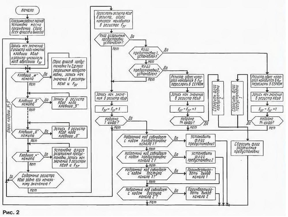
A simplified block diagram of the algorithm of the program shown in Fig. 2. After power-up occurs the system reset, reset all the flags and outputs port A. Next, the program starts to poll the keyboard. Upon detection of down key survey is suspended as long as the key is released. Protection bounce keys are software implemented. Dial the code is accumulated in register RAM of the microcontroller.
(click to enlarge)
After entering the seventh digits of the dialled code is compared with the preset code channel 1. In case of discrepancy - is compared with the code preset channel 2. When the entered code matches one of these codes, the program sets the the corresponding mode flag preset and reset your code. If not match, it is compared sequentially with the access codes to channels 1 and 2. If and with them entered code does not match, it is discarded.
After typing each number, the program checks whether the flag resolution mode preset. Making sure this happened, the program consistently clarifies whether the mode flags preset channels 1 and 2. If at least one is installed, you will jump to the mode PE. As a result of each key-press "O"to"9" in this mode is recorded in the EEPROM cell code corresponding to the numeral "erasing" were there earlier code. After entering fourteen digits (seven digits code access and seven preset code) automatically exits the preset setting (reset all flags).
To exit the preset mode can also be set by any number of digits (less fees) to, for example, when you want to modify only the code access. To do this, click on the button "'#" after dialing seven digits.
The program was prepared in the environment MPLAB [2]. When programming the crystal you should install OSC=XT, WDT=Off, if set=On, CP=Off, EEPROM data record code 00h no all addresses.
To power the module, you can use the DC voltage source is +7.5 to+15 V. the current consumption of the microcontroller DD1 from integral stabilizer DA1 at repaid the LEDs HL1 - HL3 is about 1 mA. Quartz resonator ZQ1 you can apply at any frequency 2…4 MHz (can be replaced by an RC-circuit), however note that from the clock generator frequency depends on the tone sound signals at pin 13 DD1. The piezo oscillator HA1 - SN-3.
To harmonize the logic levels at the output of channel 2 (pin 3 DD1) an actuating device of the lower circuit output resistor R12 is disconnected from stabilizer and is connected to the positive output of the power source Executive device.
The design of the module must be such as to exclude access from the outside the chains of its outputs.
The device requires no adjustment, however, before operating the user must be entered in the memory of both channels codes of their own. Do as follows. After the first power up, it takes seven times to press on click "About". The led should go on HL2 and sound a long beep signal. Then click on the "*". Now the led should go on HL1. The next operation - the user enters the fourteen digits, the first seven of which will be the access code for the channel 1, and the remaining code preset this channel.
When will be recruited fourteen digits, LEDs HL1, HL2 will go out. Re tapping seven times on the button "0" (the led should go on HL3 and sound long beep), then press "*" (the led should go on HL1), the user enters another fourteen digits for the access code and the code preset channel 2. LEDs HL1 and HL3 are extinguished. Now in the EEPROM of the module recorded their own user codes.
If you forget your access code, simply replace with a new from the preset setting. If you forgot your code preset, it can be seen only with the help of programmer reading the data EEPROM PIC controller. Code preset channel 1 is there at the addresses 19h-1Fh, channel 2 - addresses 27h-2Dh.
Note that EEPROM has a limited number of write cycles data the controller, therefore, is not recommended very often to modify the codes.
The # button can be used to forcibly reset the code when the error in the set.
Table firmware
Literature
Author: P. Redkin, Ulyanovsk