


")

Offer favorite magazine system designed by me automatic watering and spraying of plants, well-established as in the room and in the greenhouse, Conservatory and flower garden. It includes two interrelated subsystems: sensor - water (Fig. 1) and the machine electronic control (Fig. 2). And if the first can be easily assembled even for beginners, the second is best left to those who have sufficient experience and knowledge in electro - and radio engineering.
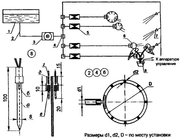
Fig. 1. Subsystem sensor - water" for auto care houseplants: 1 - tank; 2 - elastic tubing (silicone or rubber tube); 3 - electirc pump; 4 - tee; 5 - water solenoid valve; 6 - ring drip irrigation; 7 - nozzle (spray from an aerosol can); 8- self-made humidity sensor; details 3…5 - the washer of the car VAZ-2109; the amount of detail 2,4…8 - in-situ; and - bilateral foil glass fiber; b - electrode (graphite rod, pencil, 2 pieces); - contact wire winding; g o (wire type mgshv, 2); d - protective case (compound or cut vinyl tube)
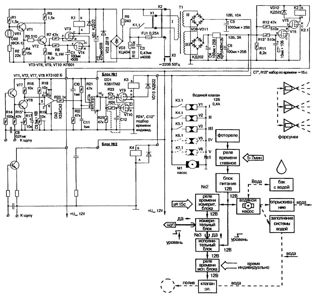
Fig. 2. Fundamental electrical and functional scheme of management automatic spraying and irrigation taking into account individual characteristics plants
Originally designed to service three (valuable for the author) of plants, the system can be used as multi. All channels absolutely identical, which greatly facilitates their installation.
The algorithm of the system is such that most of the time, the automatic (for with the exception of the duty photoelectric) sensors and de-energized. This is designed to improve the efficiency of the equipment, not to provoke stress in plants constantly flowing through the ground current, and to prevent so-called electrochemical polarization, causing a false alarm automation.
With the onset of daylight hours triggers duty photoelectric, which includes power supply and delivers in 5-7 minutes (the time interval specified main timer) 12-volt voltage to the pump motor. He begins fill in the "hydraulics" of water and spray the plants by relieving excess water through nozzles, in this case performs the function of a safety valve.
The same 12-volt voltage is applied through the time relay control 15 seconds subunit measure responsible for the clarity and accuracy of measurement soil moisture. And if the latter is lower than the desired level, set individually for each plant, the output of the circuit a signal of high level is supplied to the input of the trigger subunit management. Actuating, he opens the solenoid valve at a time determined yet one time relays, an excerpt of which is set depending on the intensity of irrigation, the growing size of the vessel and other factors.
After the specified time interval, the valve closes and water flow stops. Automatically main timer turns off the power supply, de-energizing both subsystems except for the photosensor, which is in standby mode to the next morning. If the soil moisture at the restart is normal, irrigation will not occur. The system will reduce its guardianship over the plants only mandatory morning spraying - when triggered at dawn photosensor.
Now about the features of a subsystem "sensor - water".
The humidity sensor is a probe of the strips of fiberglass, which remove most of the foil (top-only left about 10 mm). Two piece of graphite from pencil rod (length 15-20 mm each) wrapped tightly wire 10 mm and soldered to the foil strips of glass fibre laminate the opposite sides. From the top to the leads soldered the wires and all design sealed with compound.
In the device used irrigation solenoid valves, flexible transparent tube, plastic tees and the motor of the windshield wiper from the car VAZ-2109 (the capacity of the washer tank is too small, so it is better to take 25 litre plastic canister). In the electric motor to reduce noise and reduce the power consumption weakened pressure of the brushes.
Around the plant from the tube is minimized watering ring and the inner side punctured small holes. If planting seed, the tube in the ring can not to turn and move between rows. The spraying nozzle is taken from aerosol cans. These details are the flowers on the U-shaped rod and are connected in series.
Sometimes short stature or malochislennosti plants spraying can affect the readings of the probe. In this case, it should cover the cone the cap which should not come into contact with the soil. If the device is used over a large area, from one unit of measurement you can connect several probes located in different places.
Now about the work of an electrical circuit. When dimming sensor VR1 increases its resistance, which leads to the closing of the transistor VT1. On transistors VT1 - VT2 assembled Schmitt trigger to provide hysteresis in slow change of the input signal and achieve an efficient operation of relay K1.
When the gate voltage VT3 relay K1 closes the load circuit - subunit the 12 volt supply. To ensure that it was included for a limited time (5-7 min), provides for the transistor VT4 with the discharge chain R8C1. Once the capacitor C1 is discharged to the threshold value, it opens the VT4, closing the valve VT3 on a common wire, and the relay K1 is turned off. In this state diagram is until the next evening.
Subsystem sensor - water" for auto-sitting room plants
In the afternoon, the capacitor C1 discharges through the resistors R6 and R8. So, the next time light sensor relay work within the time interval specified the values of R8 and C1.
The device is powered from the mains via the transformerless circuit to decrease of energy consumption. In standby mode it consumes a current of about 30 milliamperes.
Subunit 12-volt power outlet also has a device limit time, similar to a light barrier. But the time limits are another 15 seconds user-definable circuit R14C7.
The scheme of measurements collected on the comparator, the threshold of which set a trimming resistor R19. Handles adjust R17 and R19 are paper washer is a kind of a scale with tick marks.
Engine "podstroechnik" R19 is set to the middle position. The probe is placed in the soil to the desired moisture content. The rotation of the handle R17 is selected a trigger point relay K3. Adjustment is made for each plant (each channel) separately.
The trigger on the chip DD1 ensures clarity of the relay K3. To to limit the duration of its retention (and, hence, irrigation), is entered the limiter, which is selected by the values of resistor R24 and capacitor C12. For more convenient debugging the hardware changes from one plant to another these circuit elements made in the form of a removable module. It is useful to have at hand several modules are configured at different times (from a few seconds to several minutes).
Almost all the information about the details contained in basic electric scheme. It is only possible to specify that the fixed resistors - type MINTS, and trimming - SP-3-19, and R17 and R19 can be replaced by constant resistors after measurement of different levels of soil moisture. Capacitors C1, C2, C4-C12 widely known types K50-35 and NW - K73-17 500 V. the Relay you can use any, if only their the coil was designed for 12 V, and the contacts worked reliably when switching current is 0.6 A.
Transformer, prepared or improvised, with two secondary windings, capable to give to the load at 12 V at a current of 1 A (stable for electronics) and 8 A (conventional, to power the solenoid valves and pump motor). The parameters are named with some margin, with the expansion of the device and connection of new valves at 0,4 And at each valve.
Author: S. Sablukov