


")

The proposed machine will free the owner of a suburban area of business timely watering their plants. He not only serves in an irrigation system necessary for adequate soil moisture the amount of water, but just replenish its supply in the storage tank. Parts needed to build the machine, easy to find even in remote from industrial centers of the area.
The problem of "automation" garden of in the magazine "Radio" paid a lot attention. Were offered a variety of options for its solution [1-7], each with its own characteristics. After analysis it was decided to develop own version of the machine, combining the qualities considered and deprived, if possible, have their disadvantages.
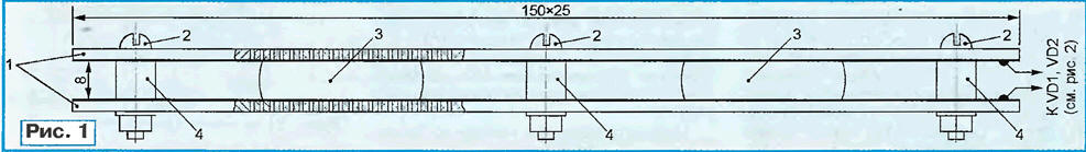
To control the watering of plants, first of all, you need a sensor responsive to the soil moisture. As shown in Fig. 1, it is made of two sided foiled glass fibre laminate plates 1 dimensions 150x25x2 In each mm. drilled by 70-80 holes with a diameter of 1.5 mm, evenly distributed the whole surface.
(click to enlarge)
Plate 1 is soldered to the foil connecting wires fixed parallel foil inside with screws 2 and insulating bushings 4. In two places between the plates has a foam insert 3 (the size of the workpiece 25x20x12 mm). The assembled sensor is wrapped around the perimeter with adhesive tape that protects from ingestion of soil particles.
The sensor is buried in the ground at a shallow depth. The foam absorbs water, penetrating through the holes in the plates, as a result of electrical the resistance of the sensor (1…2 MW in the dry state) is reduced to 40…200 Ohm when fully saturated with moisture.
The second sensor - water level in the storage tank is made of cut power cable AVVG 4x4 mm2, is introduced into the tank. The ends of four aluminum wires about 200 mm clear of insulation. Two connected together the wires form a common electrode of the sensor. The ends are fixed horizontally at the bottom of the tank. The end of the third wire placed similarly at 150 mm above.
This electrode "a Little". The end of the fourth wire (the electrode "a Lot") is located in the top of the tank sufficiently to prevent overflow away from him slice.
Diagram of the machine shown in Fig. 2. A control unit assembled on watering transistors VT1-VT3 and relay K1. While soil moisture conditions are satisfactory and the sensor resistance is low, the transistor VT1 is closed, and forming with it the Schmitt trigger transistor VT2 is open. The voltage flowing through the emitter a repeater on the VT3 transistor to the coil of relay K1, it is not enough to trigger last.
As the soil dries, the resistance of the sensor and the voltage at the base of transistor VT1 grow. At some point the voltage will be sufficient to switch trigger. The voltage across the relay coil K1 abruptly increases. When input, it closes the supply circuit of the solenoid valve, opening the access of water from the storage tank to the irrigation system or pump that draws water into it. Flashing led light HL3 green glow will show that the watering goes.
The soil moisture sensor resistance drops, the voltage on the base of the transistor VT1 becomes less than the switching threshold of the trigger that will lead to the return the device to its original state. The watering is completed.
The relay K1 when the desired humidity is achieved by adjustment adjusted resistor R3. Sometimes you have to change the value of the resistor R2.
The diodes in the emitter circuits of transistors VT1, VT2 is different from the semiconductor materials (VD4 - germanium, VD5 - silicon). This improves temperature the stability threshold of the device.
Capacitor C7, increasing response time and releasing the relay, eliminates 'bounce", often preceding the switch. He reduces to a safe the values of the amplitude of the voltage spikes at the relay coil. Diodes VD1 and VD2 with the capacitor C4 serves to eliminate the harmful effects of interference, inevitable with the big length of the wires connecting the machine with the humidity sensor.
Relay K1 - RMU passport RS4.523.330 (winding resistance of 430 Ohms). Can to apply and other, designed for switching AC circuits, frequency 50 Hz, a voltage of 250 V at currents up to 5 A. for Example, a series of PE-36 with a coil 24 DC.
The feed control device of the water in the storage tank consists of two almost identical nodes, responsive to the minimum and maximum levels. When the tank is empty, resistors R1 and R5 is maintained at the inputs of the elements DD1.1 and DD1.2 level log. 1. Chain R6C2 and R7C6 serve as a filter, suppressing crosstalk and impulse interference.
The level at the outputs of the above elements in this state - log. 0, and the outputs of the elements DD1.3 and DD1.4 - log. 1. HL1 led (flashing red glow is enabled and signals that the tank is empty. Led HL2 (green light extinguished. The transistors VT4-VT7 open.
Triggered relay K2 closes the circuit of relay coil short circuit, resulting in fires and it, and HL4 led (yellow glow) is included. Contacts short circuit.2 close the supply circuit of the pump supplying water to the tank.
Water, attained the electrode "a Little", will sharply reduce the resistance between it and General electrode. The level of the log. 1 at the input of the element DD1. 1 changes to the log. 0. In a result, the led goes out HL1 and will be closed composite transistor VT4VT6. However, through closed contacts K3.1 it will not change the status of the relays K2 and KZ and the pump will continue to work.
When the tank is filled to the electrode "a Lot", will change the state of the elements DD1.2 and DD1.4, will be led on HL2 and closed composite transistor VT5VT7. The HL4 led off, relay circuit, followed by K2 let go the anchors. The water flow in the tank will be terminated and will not resume until its level drops below the electrode "Little", then the above process will be automatically repeated.
Relay K2 - RES, passport RF4.500.131 or RAS, passport RS4.524.200. Relay circuit similarly, K1. If the pump motor power exceeding 1 kW, for his enable the required electromagnetic starter of suitable capacity, for example, the series PME-100 or PME-111. In such a case, the contacts K3.1 switching circuit the windings of the starter.
The voltage of the machine (24) even in the "field" conditions at elevated moisture poses no danger to humans. However, against accidental falling under a voltage of 220 V, for example, when damage to the insulation between the primary and secondary windings of the power transformer, it is necessary to take all measures. It is best to use the transformer windings which are in different sections of the frame. Should provide the ability to quickly automatic or manual emergency shutdown of both terminals of the primary winding from the mains.
Common wire of the device should be securely grounded, and all the produce the observance of the "Rules of organization and operation of consumer electrical installations" and fire safety measures.
Literature
Author: A. Markov, G. Tuloma Murmansk region.