


")

After reading the article A. Belsky "Evaluation of the thickness of the paint" ("Radio", 2002, № 2, p. 57), I decided to apply the described simple device for controlling the thickness of the polymer film. However, it was found that for this purpose, its accuracy is insufficient, the scale of reference is nonlinear, and its length is not used fully. These features of the notes and the author specified article.
As a result of the improvement of the measuring instrument the scheme shown in figure. Assembled on it, the instrument measures the thickness of any dielectric films, including paints and coatings in the range of 0.05… 1 mm with an accuracy of more than 5 %.
(click to enlarge)
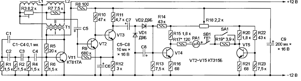
Generator transistor VT1 through a transformer T1 feeds alternating current a frequency of approximately 1000 Hz measuring bridge L1L2R3R7. Coil L1 with open magnetic circuit - the sensor. If the ends of the magnetic circuit tightly pressed against the smooth surface of a plate of mild steel, the inductance of the sensor and the maximum is exemplary inductance coil L2. The exact balance of the bridge achieve a trimming resistor R3. If between the ends of the magnetic sensor and the plate to put the dielectric film, the bridge razbalansirovat and at the entrance a two-stage amplifier transistors VT2 and VT3 will appear AC the voltage amplitude proportional to the film thickness. The amplified signal, rectified by diodes VD1 and VD2 (condenser C8 - smoothing), arrives at the input of the DC amplifier transistor VT4, to the collector through which a resistor R17 is connected microammeter RA1. A second terminal of the microammeter is connected via the button SB1 to the collector of the transistor VT5 (directly or through resistor R19 depending on the selected sub-band measurements).
With a balanced measuring bridge arrow microammeter RA1 set to zero variable resistor R18. Due to the fact that the cascades the transistors VT4 and VT5 are identical, change the ambient temperature is not causes marked "withdrawal" hands and does not introduce errors in the result measurements. When closed the switch SA1 maximum measured thickness of 0.2 mm, in open - 1 mm.
The device is fed from a 12 volt any stable source. I used the power supply of TV antenna amplifier. You can apply and battery of electrochemical cells. Voltage 7…8 is enough, so suitable battery "Krona" or "Emery". In this case, as SB1 it is recommended to set the button with two sets of contacts. The second group, connected in series in the battery circuit, will serve as a power switch that will protect the battery from discharge in the intervals between measurements.
I mounted the unit in the housing avometra Ts43101, leaving him a native microammeter. The transformer T1 is output from the transistor radio "Russia-301". In the collector circuit of the transistor VT1 is connected to its high resistance winding. Coils L1 and 12 telephone primers TA-56 with the covers and membranes.
Measuring the "table" sheet steel of 3 mm thickness with smooth and free from corrosion of the upper and lower surfaces I placed on the top panel device. Bottom inside the body pinned to the table with tin clamp coil L2 (exemplary). The coil L1 (sensor) is mounted on a table top, tucked under it measured the film, and when checking the zero - without film. To get the reference click the button SB1. This is not recommended when the sensor is not on table. The needle of the microammeter, sharply deviating, may strike the stop and bend.
Collecting and inserting the device, first check the presence of oscilloscope AC voltage on the winding II of the transformer T1. The coil L1 is tightly press it onto the surface of the measuring table and a trimming resistor R3 achieve a minimum high resistance readings of the voltmeter connected to the terminals of capacitor C8. Then, turn off the voltmeter and pressing the button SB1, variable resistor R18 adjust the microammeter RA1 to the zero mark. Programfree the scale of the instrument, placing a coil sensor film samples known thickness. The required measurement range making a selection resistors R17 and R19.
Author: V. Narizny, Bataysk, the Rostov region.