


")

Development can find its rightful place in the kitchens have gas stoves, washing and other devices with "blue fuel". Especially if the thyristor portion a homemade device to enter additional capacitor C2 with the capacitance of 0.1 µf to subsequent correction of the values of C1, RM and B2 (on the electrical circuit the diagram bold lines and text).
In this case the high voltage on the ignition electrodes and the power of the spark, almost double. Yes, and the thyristor will last many times longer due to the also, it will work in a mode that virtually eliminates the so-called reverse plectropomus. If the C2 apply K73-17 or similar compact with a nominal voltage of 400 V, no change in print the Board is not required. Enough still can move a little bit C1 to the transformer, to be released in the gap to fit the additional capacitor.
For those who will start the production e "matches" for the first time, it is worth mentioning that the magnetic core is here serves 20-mm segment of the ferrite rod F-F, round or rectangular cross-section (from the magnetic antenna of the radio). At first, this rod wrap insulation tape (2-3 layers) with subsequent placement of the high voltage winding (6x90 turns PAV-0,06), wrapping her two layers of the same tape, followed impregnation with paraffin or epoxy resin. The low-voltage winding (4 turns PAW-0.4) placed on top of high voltage.
The terminals of the windings are soldered to the corresponding pads of the PCB, manufactured to the wires going to the spark gap (and it is separated from each other and separated by the notch of the printed elements), did not reach tapering the end of the PCB is 1.5 mm and the security clearance necessarily filled epoxy that squeezed out during bonding insulating lining from 2-mm fiberglass.
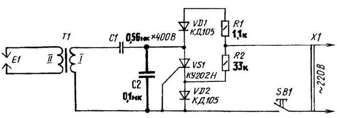
A circuit diagram of an electronic lighters
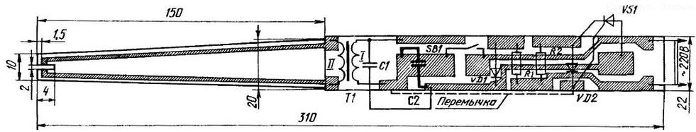
Printed circuit Board with the position of the additional capacitor C2 and the other radio component
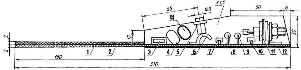
Layout electronic lighters: 1 - printed Board; 2 - insulating plate; 3 - the transformer T1; 4 - capacitor C1; 5 - button; 6 - contact spring; 7 - diode VD1; 8 - the resistor R1; 9 - resistor 112; 10 - diode VD2; 11 - thyristor VS1; 12 - body; 13 the capacitor C2.
Material for the PCB is one-sided foil fibreglass, and for cushioning the contact of a button SВ1 - stripe 15x6 mm. which cut (with giving the appropriate form) of from 0.2 mm brass or phosphor bronze.
Author: V. Radkov