


")

This device may come in handy at the cottage or farm the farm, as well as in many other cases, when required monitoring and maintenance a certain level of water in the tank.
So, when using a submersible pump for pumping water from the well for irrigation it is necessary to monitor the water level has not decreased below the position of the pump. Otherwise the pump is working at idle (without water), will overheat and fail.
Get rid of all these problems, you will help the scheme universal automatic device (Fig. 1.27). It is simple and reliability, and also provides for multi-purpose use (water or drainage).
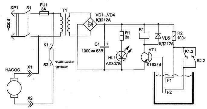
Fig. 1.27
The circuit diagram are not connected with the body of the tank, which prevents electrochemical corrosion of the surface of the tank, as is in many previously published schemes of similar purpose.
The principle of the scheme is based on the use of electrical conductivity water that gets between the plates of the sensor, closes the circuit base current transistor VT1. This triggers the relay K1 and its contacts K1.1 includes on or off (depends on the position of 82) pump.
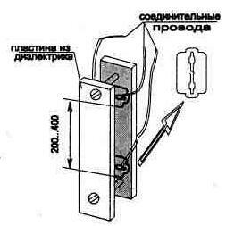
Fig. 1.28
As sensors F1, F2 can be used plates of all metals do not corrode in water. So, for example, you can use discarded stainless razor blade (see Fig. 1.28). The distance between the plates of the sensor can be 5 to 20 mm, and they are mounted on a dielectric foundations of materials that do not retain water, such as Plexiglas or Teflon.
When the power circuit switch S1, if the tank has no water, the relay K1 will not work, and the contacts K1.1 (normally closed) will provide power to the pump before the time, until the water reaches the level of sensor location F1. This will trigger the relay and its contacts will shut off the pump. Re turns on the pump only when the water level drops below the level sensor F2 (contacts K1.2 connect it to work when triggered relays). So the circuit operates in mode WATER (initial position toggle switch S2 indicated in the diagram for this mode). When a switch S2 in the position of the DRAINAGE scheme can be used for automatic control submersible pump when pumping water - disable it by reducing the water level below position sensor F2. The pump intakes should be located a little below the sensor.
The scheme used is not critical to detail. Transformer anyone, with a voltage in the secondary winding 24 To 30, associated with operating voltage of relay coil. In the scheme shall apply: relay K1 type DEAD; the C1 capacitor type K50-29 or similar. The led may be any transistor CT you can apply with the letter A, B, C or CTA, B, C.
Sensors F1, F2 is more convenient to connect to the scheme through connector (it is not shown).
With proper Assembly configuration scheme does not require.
Publication: www.cxem.net